...you may have noticed I value simplicity above all else and are only really excited by simple circuits that outperform much more complex stuff.
Me too.
But if simplicity is measured by transistor count then the Bryston OPS is about the same.
We need driver transistors either way and for serious power we need a couple of outputs anyway, just that the Bryston OPS has them connected differently.
The actual Bryston amp schematic is fairly simple and could be simplified further.
It does have some extra conceptual complexity, how to set up some of the internal compensation.
But that also provides some possibilities.
My favourite at the moment is Vanderkooy & Krauel...
I look forward to see it in my thread.
Please post your ASC for this.
Will do, I am also at work on an AD797-ish front end which also has a thread, Scott Wurcer has even responded, which was nice.
Maybe I can combine the two, an AD797-Bryston.
Since the OPS alone has 70 dB gain I should not have a problem with loop gain.😉
Best wishes
David
Never received any correspondence from Bryston's lawyers. So I think that Bryston never did apply for a patent. Chris Russell of Bryston did ask my permission to use the circuit and I granted it.
Cheers Dan
I see that this is your first post here Dan, thanks for commenting and welcome to the
forum. I'm very curious to know where you first used this configuration and was it for
a commercial product, if you don't mind my asking?
A little bit of R&D
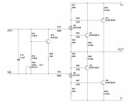
Gentlemen, a few observations I find rather interesting.
In a-la Bryston OPS arrangement with BJT drivers, the currents at both sides of the phase splitter are slightly different because of the base current of the phase splitter (emitter current is always slightly higher - you know that).
I decided to try using the Lateral FETs as phase splitters - not a new configuration, Lazy Cat used it long time ago - anyway, just curios, how it compares to the other arrangements, known as good ones. So - no gate currents, so the phase splitter is highly symmetric.
See the pictures:
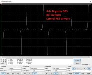
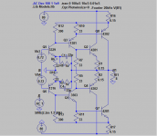
1) First picture is showing the arrangement I simulated. Showing very solid performance - low distortion when biased properly (resulting in 62.5mA at idle per output device).
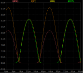
2) Collector currents of the output BJTs at the above arrangement (measured as voltage drop over the emitter resistors). Those currents drop down to zero (no surprise), however the corners are rounded enough.
For comparison:
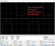
3) Collector currents in the non-switching arrangement with bias clamping mechanism. Highest performance among all the options tested at higher frequencies.
Another good option:
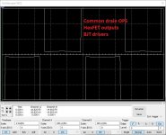
4) HexFET based OPS with fast BJT driver stage, regular bias spreader, tuned-up for the tempco of HexFETs. Surprisingly, the drain current does not touch the zero line. I don't have any good idea why it stays just above it.
Another point - the corners are rather sharp, much sharper than the ones with BJT outputs.
The last two options are live-tested, showing excellent performance.
I'm going to try the 1-st one as well - simulation looks promising.
Cheers,
Valery
Gentlemen, a few observations I find rather interesting.
In a-la Bryston OPS arrangement with BJT drivers, the currents at both sides of the phase splitter are slightly different because of the base current of the phase splitter (emitter current is always slightly higher - you know that).
I decided to try using the Lateral FETs as phase splitters - not a new configuration, Lazy Cat used it long time ago - anyway, just curios, how it compares to the other arrangements, known as good ones. So - no gate currents, so the phase splitter is highly symmetric.
See the pictures:
1) First picture is showing the arrangement I simulated. Showing very solid performance - low distortion when biased properly (resulting in 62.5mA at idle per output device).
2) Collector currents of the output BJTs at the above arrangement (measured as voltage drop over the emitter resistors). Those currents drop down to zero (no surprise), however the corners are rounded enough.
For comparison:
3) Collector currents in the non-switching arrangement with bias clamping mechanism. Highest performance among all the options tested at higher frequencies.
Another good option:
4) HexFET based OPS with fast BJT driver stage, regular bias spreader, tuned-up for the tempco of HexFETs. Surprisingly, the drain current does not touch the zero line. I don't have any good idea why it stays just above it.
Another point - the corners are rather sharp, much sharper than the ones with BJT outputs.
The last two options are live-tested, showing excellent performance.
I'm going to try the 1-st one as well - simulation looks promising.
Cheers,
Valery
Attachments
Gentlemen, a few observations...
Nice work Valery😉
I will try the FET version but with LTspice and VDMOS models, this should be more accurate because it includes sub-threshold conduction and capacitance modulation.
Sub-threshold may round-off the sharp corners you noticed.
Best wishes
David
..
I can't get excited about the full blown Bryston .. but if you can make "a decent amp with no IPS or VAS", I'm really interested. 😱
Please post your ASC for this.
OK, here is a first cut, with no attempt to match Vbe or hFE.
It's just over 1 V rms input and over 300 W output.
Distortion @20 kHz is 0.087 % mostly 2nd and 3rd.
Like you, I don't usually carry on about harmonic profile, just make it utterly inaudible, but 0.08 % is more than my usual so I checked it's OK.
Note the currents are not evenly shared on one side due to mismatch, this could obviously be improved but what is noticeable is that the distortion is still decent.
Maybe continue this in my current drive thread so as not to hijack this one.
Best wishes
David
Attachments
Last edited:
I see that this is your first post here Dan, thanks for commenting and welcome to the
forum. I'm very curious to know where you first used this configuration and was it for
a commercial product, if you don't mind my asking?
Firstly, my apologies for not getting back sooner.
First used in Thomas-Patterson 1979-1982
Differences between this and Bryston;
Opted for simpler compensation so as not to tie the Vas to output power rail trash.
Just MJE15028/29 drivers with 2N3773 / 2N6609 outputs. Circuit values were appropriate for the circuit topology.
Use of reverse bias protection diodes where required.
Sharp knee current limiter combined with a voltage clamp on the output.
Spice does not model storage times or there be more than a few vehemently complaining about the nasty clipping characteristics of this output stage.
Cheers Dan
OK, here is a first cut, with no attempt to match Vbe or hFE.
It's just over 1 V rms input and over 300 W output.
Distortion @20 kHz is 0.087 % mostly 2nd and 3rd.
Like you, I don't usually carry on about harmonic profile, just make it utterly inaudible, but 0.08 % is more than my usual so I checked it's OK.
Note the currents are not evenly shared on one side due to mismatch, this could obviously be improved but what is noticeable is that the distortion is still decent.
Maybe continue this in my current drive thread so as not to hijack this one.
Best wishes
David
My simulations show:
- Follower with LatFET drivers - pictures 1, 2 in my previous post - THD 20 = 0.07% (20V RMS @ 8 ohm);
- Non-switching OPS follower - picture 3 in my previous post - THD 20 = 0.03% (20V RMS @ 8 ohm).
Cheers,
Valery
...First used in Thomas-Patterson 1979-1982....
Spice does not model...
Nice to have more information, no Thomas-Pattersons in Australia AFAIK, do you have a schematic? It would be educational to see how the circuit evolved.
What aspects do you say Spice doesn't model?
My experience is that it simulates clip behavior pretty well and my simplistic version of the Bryston clips very cleanly.
Best wishes
David
pictures 1, 2 in my previous post - THD 20 = 0.07% (20V RMS @ 8 ohm);
Valery, my THD conditions were similar to yours except 50V RMS.
Last edited:
Nice to have more information, no Thomas-Pattersons in Australia AFAIK, do you have a schematic? It would be educational to see how the circuit evolved.
What aspects do you say Spice doesn't model?
My experience is that it simulates clip behavior pretty well and my simplistic version of the Bryston clips very cleanly.
Best wishes
David
Hello David,
On the top of page 5 right is Figure 11. Turn-Off Times in
https://www.onsemi.com/pub/Collateral/MJE15028-D.PDF
"ts" or the storage time is the item not modeled in spice.
When a BJT is driven into saturation it stays stuck on for a time equal to ts. Of course this leads to shoot through with all of its problems.
If the drivers are FETs you shouldn't have this issue. When the FET driver is in the linear region the output BJTs are still in their active region. Clean clipping in your circuit should be expected.
What spice can tell you about a circuit is that you have a mistake but it cannot tell you that the circuit is right. You have to build the circuit to determine that.
Didn't keep any schematics. Tossed them several years back.
Cheers Dan
Valery, my THD conditions were similar to yours except 50V RMS.
David, I'm just thinking... we should have probably used some way of driving the OPS, closer to VAS output conditions (high output impedance), otherwise we loose such source of distortion, as input impedance modulation (including input capacitance modulation) of the OPS, especially relevant to the version with BJT drivers.
Two voltage-controlled current sources and a simple bias spreader, shunted to ground with 1M and 10pF on each side, would model conditions, close to VAS output ones, I believe.
Cheers,
Valery
On the top of page 5 right is Figure 11. Turn-Off Times in
https://www.onsemi.com/pub/Collateral/MJE15028-D.PDF
"ts" or the storage time is the item not modeled in spice.
When a BJT is driven into saturation it stays stuck on for a time equal to ts. Of course this leads to shoot through with all of its problems.
If the drivers are FETs you shouldn't have this issue. When the FET driver is in the linear region the output BJTs are still in their active region. Clean clipping in your circuit should be expected.
What spice can tell you about a circuit is that you have a mistake but it cannot tell you that the circuit is right. You have to build the circuit to determine that.
Didn't keep any schematics. Tossed them several years back.
Cheers Dan
Hi Dan,
A very valid point - a few considerations though.
I normally try to design the power amplifier in a way that clipping happens in the VAS stage, allowing much faster recovery. This approach leads to somewhat reduced energy efficiency (OPS rail voltages are higher than they could be), however nice clean clipping is worth sacrificing some efficiency, I believe.
In my experimental prototype, I used C2922/A1216 outputs and C4382/A1668 drivers (Sanken). Those drivers have got twice as much ts, comparing to the output devices, however I did not have any issues, abusing the prototype with hard clipping, square waves up to 1MHz, etc. With lateral FETs as the drivers, there seems to be no issue at all, as you just mentioned.
I had a rail-to-rail shoot through in the other prototype with rather conventional EF3 arrangement and MJ21193/94 at the output, running a sine wave sweep 100Hz-1MHz - at around 300-500KHz the OPS has self-destructed.
I don't know their ts value, but it looks like it's higher for about an order, comparing to the modern RET devices.
Cheers,
Valery
...Turn-Off Times in
https://www.onsemi.com/pub/Collateral/MJE15028-D.PDF
"ts" or the storage time is the item not modeled in spice.
When a BJT is driven into saturation it stays stuck on for a time equal to ts.
Unfortunately there is no schematic of the circuit used for the test, and some of the annotations don't make sense to me.
"Ib1=Ib2" ?
Spice itself can model the various capacitances in a transistor, even how they are modulated as bias is varied, and forward and reverse transit times.
I suspect your observation may be the result of bad models with certain parameters not included rather than inherent to Spice.
Hard to believe that such a major issue would be omitted from Spice for more than 40 years, do you have a reference?
Best wishes
David
... we should have probably used...closer to VAS output conditions...
In my previous studies of EF and CFP OPS I started with zero source impedance, just like here, but I did experiment with the effect of source impedance once I understood the baseline case.
I was surprised at the sensitivity of some OPS to source impedance so I think you raise an important point.
This is essentially the discussion in my "Current Driven OPS" thread, perhaps further comments should be there.
Best wishes
David
Ib1=Ib2 meaning the base turn on current = the base turn off current.Unfortunately there is no schematic of the circuit used for the test, and some of the annotations don't make sense to me.
"Ib1=Ib2" ?
Spice itself can model the various capacitances in a transistor, even how they are modulated as bias is varied, and forward and reverse transit times.
I suspect your observation may be the result of bad models with certain parameters not included rather than inherent to Spice.
Hard to believe that such a major issue would be omitted from Spice for more than 40 years, do you have a reference?
Best wishes
David
G U M M E L - P O O N B I P O L A R M O D E L
M O D E L D E S C R I P T I O N
P A R A M E T E R E X T R A C T I O N
by F.Sischka
http://ftp.elo.utfsm.cl/~lsb/elo102/ejercicios/GP_DOCU.pdf
on pp 85
Limitations of the Gummel-Poon Model
...
The modeling of the saturated region in the output characteristics (VCE < 0.5V) lacks of specific parameters. Therefore the model cannot cover modern transistors in this range (quasi-saturation).
...
Most modern treatments for spice don't even mention storage time because it is not in the G-P model. The above brief note is all that I could find in the literature. The G-P model used in spice is inaccurate when the cb and be junctions are both forward biased.
Is it necessary to model storage time behavior? Not really, as a circuit designer would be aware of it and take the appropriate actions.
Cheers Dan
...by F.Sischka
http://ftp.elo.utfsm.cl/~lsb/elo102/ejercicios/GP_DOCU.pdf
on pp 85
...Therefore the model cannot cover modern transistors in this range (quasi-saturation).
Nice reference, thanks, I was completely unaware of it.
But I note that the quote about quasi-saturation is in the "Forward DC Model..." section.
Limitations of Spice for quasi-saturation DC (or quasi-static/low frequency) have been discussed in this forum and use of the quasi-saturation parameters that are available in LTSpice, as extensions to GP.
But this is distinct from hi frequency, non minimum phase delays.
I don't see any mention of this in your reference at first look.
Will study it more, first impression is that there is a lot of material that deserves close attention, thanks once more.
Best wishes
David
Yes there are extensions for quasi-saturation that have been discussed here, but from what
I've read here no one has gotten them to work. If you have a reference for them working, I'd
like to see it. I should probably look on the LTspice yahoo group.
Guru Zan, could you post your transistor models please.OK, here is a first cut, with no attempt to match Vbe or hFE.
It's just over 1 V rms input and over 300 W output.
Distortion @20 kHz is 0.087 % mostly 2nd and 3rd.
Like you, I don't usually carry on about harmonic profile, just make it utterly inaudible, but 0.08 % is more than my usual so I checked it's OK.
Note the currents are not evenly shared on one side due to mismatch, this could obviously be improved but what is noticeable is that the distortion is still decent.
I'm trying to replicate your results. I'm assuming the Cordell models are OK but what do you use for 3329 & 1316?
Firstly, my apologies for not getting back sooner.
First used in Thomas-Patterson 1979-1982
Differences between this and Bryston;
Opted for simpler compensation so as not to tie the Vas to output power rail trash.
Just MJE15028/29 drivers with 2N3773 / 2N6609 outputs. Circuit values were appropriate for the circuit topology.
Use of reverse bias protection diodes where required.
Sharp knee current limiter combined with a voltage clamp on the output.
Spice does not model storage times or there be more than a few vehemently complaining about the nasty clipping characteristics of this output stage.
Cheers Dan
We appreciate your input, thanks for joining in whenever you have a chance. Very interesting to hear from the designer.
I'm looking for a schematic for one of your amps not having much luck.
Yes there are extensions for quasi-saturation that have been discussed here, but from what I've read here no one has gotten them to work. If you have a reference... I'd like to see it...
You could start here😉http://www.diyaudio.com/forums/software-tools/256643-sanken-2sc4883-2sa1859-spice-models-quasi-saturation.html#post3935643
Why did you think they didn't work?
Best wishes
David
Guru Zan, could you post your transistor models please.
Didn't I send you them, included with the IXYS FETs?
In any case, this was just a quick draft to look at the concept, the precise values don't matter, should have similar behavior with more or less equivalent transistors in each section.
Actually that would be informative in itself, try "home brand" transistors and see how much it needs to be tweaked.
If you don't have the inclination to fiddle with it then I can resend my models.
Best wishes
David
- Status
- Not open for further replies.
- Home
- Amplifiers
- Solid State
- Bryston 3BIII SPICE Simulation - Current Sharing and Output Stage