I got abanico points. That's what I am afraid. How far the repair would go then the cost would be associated with, no idea as I am just so new to this field. Love to have this fixed as I never own a considered good amp. I will contact Bryston regard to a new pair of BR6521/6522 and this may be less problem with Bias/ offset.
BTW, what are bias offset pots, where are they located and how to adjust...? my head spinning again LOL
P.S. I will try to identify bias offset pot tomorrow morning (yawn)
BTW, what are bias offset pots, where are they located and how to adjust...? my head spinning again LOL
P.S. I will try to identify bias offset pot tomorrow morning (yawn)
Umm .. not sure who mentioned 'bias offset pot', but as far as I know they'll always be separate pots. Also, pretty sure neither of my older Bryston models has an offset adjustment. (But it has been a few years since I've been in there.)
But you'll want to adjust the bias pots to minimum before applying power withOUT the series-lamp/dim-bulb(whatever-we-call-it) tester (glad you have it). Maybe only fit one fuse at a time.
Have a good sleep; read you tomorrow.
Cheers
But you'll want to adjust the bias pots to minimum before applying power withOUT the series-lamp/dim-bulb(whatever-we-call-it) tester (glad you have it). Maybe only fit one fuse at a time.
Have a good sleep; read you tomorrow.
Cheers
Last edited:
There are no offset pots in this amplifier as far as I know, just bias pots. As Rick states, set them to minimum before powering up.
If you decide not to repair the amplifier let me know. I live nearby and would be happy to take it off your hands.
Take care,
Doug
If you decide not to repair the amplifier let me know. I live nearby and would be happy to take it off your hands.
Take care,
Doug
1/ Removed 2 shorted TO-3: no sign of over heat, is it good or bad signs (maybe caused by something else...)
2/ Bias, look like a circle thingy (picture attached) and to be adjusted by phillips screw driver, is it the right one?
3/ show me in details how, where to hook up Volt meter...what to watch for..
Thanks,
2/ Bias, look like a circle thingy (picture attached) and to be adjusted by phillips screw driver, is it the right one?
3/ show me in details how, where to hook up Volt meter...what to watch for..
Thanks,
Attachments
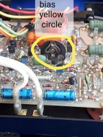
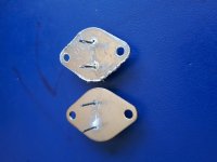
These type of transistors usually don't look any different when they have failed, remember that you should replace all 4 TO3 transistors. Yes that is the bias adjustment potentiometer, a small flat screwdriver works well for adjusting it. Here is the official Bryston procedure for testing and biasing the amplifier:
http://old.bryston.com/PDF/Other/3B_4B_Pre-NRB_TECH_REF.pdf
There is a lot of other repair information that you can find if you do some searching.
Take care,
Doug
http://old.bryston.com/PDF/Other/3B_4B_Pre-NRB_TECH_REF.pdf
There is a lot of other repair information that you can find if you do some searching.
Take care,
Doug
Oh it uses my favorite, an open track carbon film bias trim pot. Aren’t those illegal now?
Last edited:
I serviced one of these amps a few months ago. The lousy carbon bias pot on one channel was toast and took out not only a pair of outputs,but a driver and the bias transistor as well. The bias transistor is bolted under the pcb. Check it as well. It's the mje182.
Replace the trimpot with a cermet type and I suggest you replace on both channels,because sooner or later these will fail. By the way I used MJ15003/4 and MJE15034/35 for the drivers.
Replace the trimpot with a cermet type and I suggest you replace on both channels,because sooner or later these will fail. By the way I used MJ15003/4 and MJE15034/35 for the drivers.
Last edited:
Gosh, I hope not -- their condition is plainly visible. If it needs a squirt of Cramolin, you don't have to struggle to get it in.
Yes, and it's a design that I consider (my humble opinion) improper: Intermittent wiper opens the bias -- maximum current through all succeeding stages. I alway fit the trimmer shunting the BE junction so when it goes open you get very low bias. Horrible crossover distortion is better than smoked drivers and outputs.
Yes, and it's a design that I consider (my humble opinion) improper: Intermittent wiper opens the bias -- maximum current through all succeeding stages. I alway fit the trimmer shunting the BE junction so when it goes open you get very low bias. Horrible crossover distortion is better than smoked drivers and outputs.
Last edited:
Got your PM with the 1985 build-year reference. Figured I better come back here where others can 'check my work'.
Also have a couple questions for the broader audience:
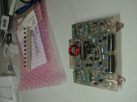
- I can't think of any good reason - from a layout standpoint - for the outputs to be polarity-paired diagonally, which is what your 2nd pic, original post shows
I'm gonna go have a peek under the little snap-on veils on a 4B (1977 vintage); you might check that on your working left channel.
- Also can't think of any good reason for 220V amps to be biased different than 120V-ers -- page 5 of the link in post #25 - big thanks The Peasant 😉
-- Mayhaps some kind of safety-sanctioning-body drivel?
If you grab down your very own copy of that, Troy9018, you may have all you need. Still studying it myself -- cheeze-Louise the input options ..
Cheers
Also have a couple questions for the broader audience:
- I can't think of any good reason - from a layout standpoint - for the outputs to be polarity-paired diagonally, which is what your 2nd pic, original post shows
I'm gonna go have a peek under the little snap-on veils on a 4B (1977 vintage); you might check that on your working left channel.
- Also can't think of any good reason for 220V amps to be biased different than 120V-ers -- page 5 of the link in post #25 - big thanks The Peasant 😉
-- Mayhaps some kind of safety-sanctioning-body drivel?
If you grab down your very own copy of that, Troy9018, you may have all you need. Still studying it myself -- cheeze-Louise the input options ..
Cheers
Yup -- Whoever installed those outputs put 'em in wrong!
The PNP's (orig(*) 2N6609) should be in the two positions toward the front of the amp. The NPN's (orig(*) 2N3773) should occupy the two locations toward the rear of the unit. Furthermore, since these modules are 'ambidextrous', the left channel is exactly the same layout.
Cheers
* - 'originally', as in p/n's on the schematic
Last edited:
I am reading it and try to locate the measuring points (4 - 5W resistors) . There should be 2 places to measure for adjusting the bias (need to be confirmed?).
Regards to TO-3 outputs layout, it's the same for both sides.
Regards to TO-3 outputs layout, it's the same for both sides.
Yes. Those big green puppies are the ones. Since the output should be unloaded for the measurements, the value should be substantially the same for any of the four of them. If it isn't, there's a transistor mismatch.
Umm .. sorry, but I don't see how the working channel could be (the same as the dead right channel) -- without a fair amount of diagonal cross-wiring -- the driver is up at the top (module in 'right channel' position as you face the front of the amp), and each serves a pair of outputs. The 0021's should both be together under their driver; the 0022's together under theirs.
Cheers
edit: Yup, I've now checked it seven ways from Sunday, including on my 4B, and the outputs are paired-up vertically, each pair having its own personal TO-220 driver.
Last edited:
- Home
- Amplifiers
- Solid State
- Bryston 3B Transistors check and replace