Thanks Ian, figured there must be a standard but then I'd hate to order, wait, disable my amp AND THEN realize I had the wrong size 😩
cbc6403 I want to order the main caps before disabling my amp.... do you remember the lead spacing on the main caps (snap in I believe). I'm going to go with the Nichicon Gold but want the things to fit and I'm not sure if these are a standard spacing. Thanks
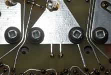
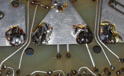
As Ian said, the spacing is a 10 mm standard, although on the newer amplifiers, I had to drill the holes out a bit to get the wiggly, snap-in leads to fit in the old holes. It's a single sided board and there is lots of copper, so it's not really tricky to do this.
If you have a really old 2B, it used 6000 uF Sangamo caps with screw terminals, which had much larger mounting holes in the circuit boards. However the spacing is still compatible with the newer snap-in caps, so you're still OK. I added a bit of wire across the copper side of the board to give some more surface area for the solder to stick to. It would likely not be an issue unless your amp was rattling around in a vehicle.
I've attached a couple pictures (I hope) of the old style caps and the fix with modern, snap-in types.
GTD
Attachments
Last edited:
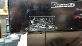
Just picked up one of these Bryston 2B's off fleabay. This is also one of the original ones. Has 6000uf Mallory caps.
A little dirty inside, but works well. Looks like most, if not all the parts are still available. A few from fleabay, but nonetheless.
I may not do anything other than clean it up a bit. I played it all afternoon in the shop and didn't have any problems. I may buy a bag of spare parts while they are all still available.
I'm probably going to use this as a center channel amp. It's easy to bridge by just using the left channel input and both of the "red" speaker connectors. Might make a great center channel amp.
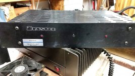
Here are a few pics of the old girl.
gabo
A little dirty inside, but works well. Looks like most, if not all the parts are still available. A few from fleabay, but nonetheless.
I may not do anything other than clean it up a bit. I played it all afternoon in the shop and didn't have any problems. I may buy a bag of spare parts while they are all still available.
I'm probably going to use this as a center channel amp. It's easy to bridge by just using the left channel input and both of the "red" speaker connectors. Might make a great center channel amp.
Here are a few pics of the old girl.
gabo
Attachments
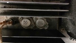
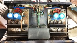
Very old girl, indeed. These cool driver transistors were RCA 40409 and RCA 40410, often to be seen in the early 70s, if memory serves🙂
Very old girl, indeed. These cool driver transistors were RCA 40409 and RCA 40410, often to be seen in the early 70s, if memory serves🙂
Didn't know they were that old, cool. They are both still available on fleabay, and at reasonable prices too. You can get a pair, one each, for $20. Same with all the other parts, everything seems to be available.
I will definitely pick up some of these just for spare parts.
gabo
A few small discoveries on my amp. The toggle switch for mono-stereo is completely broken off. Didn't realize it because I didn't realize there was a switch! 🙂
Need to find the spec on that switch.
Not that it's a big deal, but two of the output transistors have been replaced. The originals are 2N6609/2N3773 pairs, which one channel is. The other channel has MJ15001/MJ15002's, so they've been replaced.
Not sure if it's best to stick with the original 2N6609/2N3773 combo or if a replacement is an upgrade. There are a number of MJ15XXX transistors that would work. All of those options are still available.
While I'm in there I probably should just go ahead and replace the caps. Mine has the screw terminal 6000uf versions. Easy enough to replace with snap in caps per cbc6403's suggestion.
gabo
In looking around, I guess the 40409/40410 combination was used in many many amps back in the day. Everything from McIntosh stereo amps to guitar amps.
On ebay these days, there are many 40409/40410 transistors available from "Harris."
Not sure if you would call these "fakes" or just the modern version from Harris.
Are these Harris transistors any good? How do they compare with originals? Originals can also be found (buyer beware) from a few individuals, but are very pricey. I've even seen one pair for $150.
There are also quite a few transistors that could be used in their place. Actually since they are "driver" transistors and how the circuit is set up, there are many things you could substitute.
So the real question is, what does one do these days when replacing a 40409/40410 combo? And this is really just a question of interest to me, the ones I have are working just fine and I will not be replacing them. Just a question to learn more and have in my back pocket should I run across these in the future.
gabo
Bryston 2B-LP
Hi All,
I have many 2B-LP amplifiers and I need to recap all of them. In some amps both board have 3 x 470uf/16v per board with 2/4700/50v and some other amp have 1 x 470uf/16v, 2 x 220uf/10v per board with 2/4700/50v. Do you know if it's possible to replace all 220uf/10v by 407uf/16 without problem. On the board where are located the 220uf/10v, I have two holes punched in the board to place a 470 uf/16v and at this same place I also have a silk screen printed note " 470 uf/16v".
I can or I cannot replace the caps values without problem ?
Thanks for your advice.
Those 2B-LP's are totally different than the original 2B I have. However, sounds like someone replaced those caps before, maybe putting two 220uf/10v in parallel to create a 440 instead of just replacing the 470s. From looking at the schema I have for the LP, I only see 3 470's. But it could also be a different version of the boards.
Either way, I don't see a problem replacing those with 470uf/16v caps, that may be what was originally there.
gabo
Last edited:
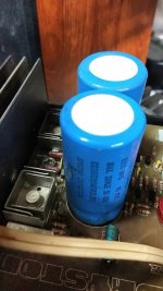
In case anyone else ever needs to replace caps in one of these Bryston amps.
Kemet has a cap that is 7500uf, 63v, screw terminals, that fits perfectly. Even the screw threads are the same as the original, so swapping them out was as simple as unscrewing and removing the old, screwing in the new ones.
Here's the cap at mouser.
ALS81A752DA063 KEMET | Mouser
Also, if you need to replace the mono-stereo switch, this one also fits perfectly in the holes.
2M1-SP3-T1-B1-M2QE Carling Technologies | Mouser
On another note, this is quite possibly the easiest to work on amp I have ever opened up! The layout is awesome, just a few screws on the bottom and you can unplug a channel board from a connector and remove it. Makes it dead easy to work on, kudos to Bryston. If all their amps are this well laid out, I need to get a few more 🙂
gabo
Last edited:
Apologies being late to read this thread, but I thought it may be helpful to share my recent experience repairing an early series of the Bryston 2B power amplifier, serial number 2930.
Report, “Bryston 2B Power Amplifier repair - Hints and Lessons Learned” is posted over at the AudioCircle site in their Vintage audio category.
https://www.audiocircle.com/index.php?topic=184949.0
Brief text extract from repairing the 2B:
* The power supply capacitors I replaced with new Kemet ALS80A 103 DB 063, a plain can type that readily installs on the 2B circuit board, with added benefit of higher rating 10,000 uF / 63V, 105 Deg C.
* Please take care when ordering capacitor replacements. The Kemet ALS81A series have a threaded mounting stud (which is not needed), that makes for a longer overall length and may not fit within the 2B chassis - which I found out the hard way. Whereas the Kemet ALS80A series being a shorter length plain can type, even with a higher capacitance rating fits nicely within the dimensions of the 2B chassis (Fig. 3).
* The three smaller electrolytic and two tantalum capacitors on each circuit board were tested and all within specification and functional, but as a precaution replaced them with higher grade new.
* Left channel power transistor 2N3773 replaced with higher rated MJ15024. Power transistor 2N6609 replaced with higher rated MJ15025. Renewed the TO-3 size mica insulators and silicon insulating grease.
* Replaced glass cartridge fuse with a standard 3A / 30 mm type.
* The original 10K bias potentiometer was an open-face type (Fig. 2) and although still working had captured some dust over the years, as precaution replaced with closed type potentiometer of same rating 10K (Fig 4).
Please note your version of Bryston 2B power amplifier might have different specification from my early version, nevertheless I hope the information in this report may be helpful.
Thank you,
John

Re: Bryston 2B Power Amplifier repair - Hints and Lessons Learned
Dear John,
Thank you for your very informative "Lessons Learned" on the overhaul of your Bryston 2B and also your similar contribution on a Bryston 3Be.
Both write ups were very useful for me (also the accompanying photo's).!
Question for you:
I have a question on preventive capacitor replacement in a Bryston 4B ST Amp i.e.
Could you please comment on my selected tentative replacement type for the axial, and radial electrolytic capacitors on the "Amp PCB" and the "extension PCB" boards?
(NB the main Power Supply buffer capacitors (8 X Nichicon 5600 uF, 100V, 105 deg. C) still measure fine (capacitance and ESR) , and I do not intend to replace those, for the time being.
The small Elco's ones on the boards are probably OK as well, but I would like to replace them preemptively, just to be sure!
This especially applies for the tantalum caps, since I have bad experiences with those in Tektronix and STUDER equipment;
The voltage de-rating (now after 40-45 years) seem to have been too low, and they might/do fail with massive short-circuits), as you have experienced, yourselves.
Background
I recently purchased from a Medical Doctor, a Bryston 4B (originally an NBR) vintage: Mid 1990's, but upgraded by BRYSTON Canada in late 2004 to ST specs.
(the special Bryston box used for sending the Amp to and fro Canada is still there, inclusive of the Rep details who handled the order in Canada!).
Talking about an excellent service: The importer in the Netherlands (MaFiCo) sent me, a few weeks ago, free of charge, 14 screws for the top plate, because somebody had damaged them, by not using a proper Robbertson socket.
Anyhow, my Bryston 4B - ST "Metisse " is playing fine with my transmission line speakers (IMF Studio Monitor, later: TDL).
I'm happy with the Amp!
Back to the electrolytic capacitors:
There are (see schematic), red boxes:
8 X Axial 470uF 16V
4 X radial 470 uF 16V
2 X axial 2200 uF 16V (AUDIO FEEDBACK LOOP)
4 Tantalums 1.5 uF 35V
There are nowadays preciously few suppliers for axial capacitors.
I selected Vishay 118 AHT , 125 deg. C, 8000 Hrs LL types for for the axial and Vishay 146rti 125 deg. C , 4000 Hrs LL for the radial types.
https://www.vishay.com/docs/28334/118aht.pdf
https://www.vishay.com/docs/28401/146rti.pdf
These seem to be relatively contemporary types (only introduced by Mouser, 2 years ago).
I intend to use higher voltage ratings resp. 63V for the 8 470 uF, 40V for the 2 2200 uF axial ones and 63V for the 4 radial 470 uF ones, since these easily fit on the allotted spaces.

The tantulums, I (standard) replace by film capacitors, in this case WIMA MKS2 2.2uF 63V with 5mm spacing.
(I have good experience with those WIMA's in Revox and AKAI equipment).
Questions:
+ Could you please comment whether the axial Vishay 118 AHT 2200 uF 40V 125V is suitable for it's duty in the Audio feedback loop
and hence perhaps more critical?
+ Do I perhaps require a "special Audio Capacitor" on that location?
Thanks for comments and suggestions
I found this discussion in the Bryston Audio Circle Forum
""
Okay, I spoke to Mr. X and would like to share his expertise on this particular 3B circuit.
His response was that the 220uF capacitor is a protection circuit timing capacitor. The 220uf/6.3v capacitors carries a small amount of DC voltage and you can use either a polarized or non-polarized capacitor when replacing it.
The 470uF/16v are the feedback capacitors in this design and it sees no offset at all. That capacitor can also be polarized or non-polarized capacitor too. M, X also made it clear that if you use a polarized capacitor, its orientation is not critical.
According to Mr. X, Bryston has tested non-polarized capacitors in both positions for the 3B amplifier and noticed no change in performance or behavior but they tend to use polarized for both circuit positions to this day.
Hats off to Bryston for supporting their products with such willingness and promptness in order to help out a fellow Bryston owner.
""
NB On the later 3B /4B amps the 220uF 6.3V capacitors have been replaced by 470uF 16V ones ( 3B 4X, 4B 12X).
The 470uF16V feedback capacitor were replaced bu a 2200uF 16V capacitors (2X)
The latter ones , are the ones which you replaced by Nichicon Fine Gold samples.
I attach the 3B/4B ST schematic for your info.
Regards,
Martin
Hello Martin,
No rush, was curious how you made out with your Bryston 4B ST repair, hopefully all went well.
I was reminded of your pleasant reply and follow-up when I recently posted another report, "Bryston 3Be Power Amplifier - Adjusting and Minimizing DC Offset", which you might find useful.
https://www.audiocircle.com/index.php?topic=188637.0
I'm not saying there is anything wrong with your Bryston 4B ST, but if you're still working on your 4B ST, I found with my Bryston 3Be the DC offset measurement was a straightforward and easy check to make, and in fact even after 30-years it was remarkably stable and well within specification.
From looking at your 4B ST circuit diagram the offset adjustment (if needed) would appear to be very similar.
Again, hopefully all went well with your 4B ST repair.
Thank you,
John
Hi John,
All well, I hope!!
I was pleasantly surprised to se your contribution "how to Adjust Bias in a Bryston-3be" in https://www.audiocircle.com/index.php?topic=188637.0 .
Again, I was impressed, by the depth, breadth and thoroughness of your latest contribution.
Sorry, that I did not react earlier; I only discovered your topic yesterday.
Please find below :
A summary of my recent activities , which were completely sidetracked into miscellaneous topics, yet still with the FOCUS on the planned overhaul of this Amp:
BRYSTON-4ST/NBR , ( an official BRYSTON Overhaul/Revamp from a -4B NBR Chassis into a ST by Bryston, Canada (in late 2004), with still 3/4 year "guarantee left!!).
Spoiler : I have not overhauled it , yet. It is playing very fine (after the old capacitors had spontaneously been reformed again), after long storage.
But here is a summary of the status of the "project"
1) Initially ordered and received 125 deg Vishay Axial Capacitors for the AMP control boards
2) Reordered and received Nichicon Audio quality ones on your advise, for same purpose (however, not strictly necessary , I think).
3) Ordered and received 8 X Cornell Dublier Power supply caps (identical to your ones, from MOUSER, by my local supplier).
4) Ordered 12X MJ211293 / MJ 21194 pairs from a Dutch supplier (intended as a future Back Up for a repair, if ever required)!
Despite claims to the contrary, from that supplier I got a strong suspicion that these were FAKES, rechecked the "visual indicators" with the Dutch forum https://www.circuitsonline.net/
I could now prove by visual indicators but also by my Peaktech DCA55, that these were certainly "not the real thing".
Sent them back (a considerable sum had been paid: the price paid was certainly not an indicator for them being FAKES) and I got my Money back with no squabbles.
5) Ordered the MJ21193G and 21194G 's from resp. Mouser and Digikey.
Lead times are extremely long. I received these the day before X-mas 2023.
6) By this Fake Business, I got interested in identifying transistors by Transistor Curve Trace testing.
Bought a kit from Thailand (to be used with a scope) , built it and was able to characterize ( hFE) the Real On-Semi MJ21193G/94 transistors up to Collector Currents Ic of some 0.2 A.
NB The PEAKTECH DCA55 only measures at one Ic = 2.5 mA
NB A previous poster on Audiocircle also bought this Thai Tracer KIT.
see:
https://www.audiocircle.com/index.php?topic=183966.0
I was inspired by this fellow (later I got similar advice from Dutch technicians: The schematic was initially published in the Dutch magazine ELEKTOR in the late 1980's)!)
However that Audiocircle thread suddenly ended with no conclusion/finalization.
(I suspect in the end, the TS eventually realized that he had bought Fakes from China and had finally discovered it !!
7) I was also instructed on
https://www.circuitsonline.net/forum/view/163143
how to measure (manually) hFE vs IC (Ib as parameter ) transistor characteristics, using 2 lab power supplies (basically like the Tektronix Curve tracers do, but in a manual fashion) and some accurate DMM's.
8) I could now convincingly see that the ON-SEMI 21193G/94G from MOUSER/DIGIKEY were REAL and the curves matched exactly the Datasheets;
But also the Thai kit Tracer tester and the PEAKTECH DCA55 matched transistor type curve (in their "domain").
So the measurements were now OK.!!
https://www.circuitsonline.net/forum/view/163374
https://www.circuitsonline.net/forum/view/157871/3
https://www.circuitsonline.net/forum/view/157871/4
I now could start matching those power transistors .
9) ESP (Eliott Sound Products) Australia shows a little schematic #106 to make that that "power supply matching process" much more faster;
I'm on the verge of constructing his suggested schematic, using a dual power supply, 3 accurate DMM's and an array of toggle switches.
https://sound-au.com/project106.htm
All of the above was extensively discussed on the Dutch Sitehttps://www.circuitsonline.net/ ( I learned a lot in the process!).
(BTW I also presented your tantalum cap experience in the Bryston-2B, which initially met disbelief with some "specialists", quite in contrast to the "the real designers" on https://www.diyaudio.com/community/
10) But All of the above had stalled the planned recap on my Bryston-4B ST/NR "Metisse" .
It is this AMP, which I currently use continously, so I must complete the recap within 1-2 days.
But, as usual, there are so many things to do/attend, so this Bryston-4B Recapping has been a bit on the Backburmer!
(I had even to buy to some special tools e.g the funny (but well designed) "Robertson" square bits (R1, R2 , R3) which are needed to open up the AMP!!
Concluding:
I think that I first will buid that Elliot Kit #106 , next, Match my transistors and only thereafter overhaul the Bryston-4 ST/NBR
(As such , I can quitely progress as time permits and if the outside wheather is bad).
Cheers, thanks for all your contributions and the nice Photographs! Extremely Handy/useful!
Martin

.jpg")
.jpg")

All well, I hope!!
I was pleasantly surprised to se your contribution "how to Adjust Bias in a Bryston-3be" in https://www.audiocircle.com/index.php?topic=188637.0 .
Again, I was impressed, by the depth, breadth and thoroughness of your latest contribution.
Sorry, that I did not react earlier; I only discovered your topic yesterday.
Please find below :
A summary of my recent activities , which were completely sidetracked into miscellaneous topics, yet still with the FOCUS on the planned overhaul of this Amp:
BRYSTON-4ST/NBR , ( an official BRYSTON Overhaul/Revamp from a -4B NBR Chassis into a ST by Bryston, Canada (in late 2004), with still 3/4 year "guarantee left!!).
Spoiler : I have not overhauled it , yet. It is playing very fine (after the old capacitors had spontaneously been reformed again), after long storage.
But here is a summary of the status of the "project"
1) Initially ordered and received 125 deg Vishay Axial Capacitors for the AMP control boards
2) Reordered and received Nichicon Audio quality ones on your advise, for same purpose (however, not strictly necessary , I think).
3) Ordered and received 8 X Cornell Dublier Power supply caps (identical to your ones, from MOUSER, by my local supplier).
4) Ordered 12X MJ211293 / MJ 21194 pairs from a Dutch supplier (intended as a future Back Up for a repair, if ever required)!
Despite claims to the contrary, from that supplier I got a strong suspicion that these were FAKES, rechecked the "visual indicators" with the Dutch forum https://www.circuitsonline.net/
I could now prove by visual indicators but also by my Peaktech DCA55, that these were certainly "not the real thing".
Sent them back (a considerable sum had been paid: the price paid was certainly not an indicator for them being FAKES) and I got my Money back with no squabbles.
5) Ordered the MJ21193G and 21194G 's from resp. Mouser and Digikey.
Lead times are extremely long. I received these the day before X-mas 2023.
6) By this Fake Business, I got interested in identifying transistors by Transistor Curve Trace testing.
Bought a kit from Thailand (to be used with a scope) , built it and was able to characterize ( hFE) the Real On-Semi MJ21193G/94 transistors up to Collector Currents Ic of some 0.2 A.
NB The PEAKTECH DCA55 only measures at one Ic = 2.5 mA
NB A previous poster on Audiocircle also bought this Thai Tracer KIT.
see:
https://www.audiocircle.com/index.php?topic=183966.0
I was inspired by this fellow (later I got similar advice from Dutch technicians: The schematic was initially published in the Dutch magazine ELEKTOR in the late 1980's)!)
However that Audiocircle thread suddenly ended with no conclusion/finalization.
(I suspect in the end, the TS eventually realized that he had bought Fakes from China and had finally discovered it !!
7) I was also instructed on
https://www.circuitsonline.net/forum/view/163143
how to measure (manually) hFE vs IC (Ib as parameter ) transistor characteristics, using 2 lab power supplies (basically like the Tektronix Curve tracers do, but in a manual fashion) and some accurate DMM's.
8) I could now convincingly see that the ON-SEMI 21193G/94G from MOUSER/DIGIKEY were REAL and the curves matched exactly the Datasheets;
But also the Thai kit Tracer tester and the PEAKTECH DCA55 matched transistor type curve (in their "domain").
So the measurements were now OK.!!
https://www.circuitsonline.net/forum/view/163374
https://www.circuitsonline.net/forum/view/157871/3
https://www.circuitsonline.net/forum/view/157871/4
I now could start matching those power transistors .
9) ESP (Eliott Sound Products) Australia shows a little schematic #106 to make that that "power supply matching process" much more faster;
I'm on the verge of constructing his suggested schematic, using a dual power supply, 3 accurate DMM's and an array of toggle switches.
https://sound-au.com/project106.htm
All of the above was extensively discussed on the Dutch Sitehttps://www.circuitsonline.net/ ( I learned a lot in the process!).
(BTW I also presented your tantalum cap experience in the Bryston-2B, which initially met disbelief with some "specialists", quite in contrast to the "the real designers" on https://www.diyaudio.com/community/
10) But All of the above had stalled the planned recap on my Bryston-4B ST/NR "Metisse" .
It is this AMP, which I currently use continously, so I must complete the recap within 1-2 days.
But, as usual, there are so many things to do/attend, so this Bryston-4B Recapping has been a bit on the Backburmer!
(I had even to buy to some special tools e.g the funny (but well designed) "Robertson" square bits (R1, R2 , R3) which are needed to open up the AMP!!
Concluding:
I think that I first will buid that Elliot Kit #106 , next, Match my transistors and only thereafter overhaul the Bryston-4 ST/NBR
(As such , I can quitely progress as time permits and if the outside wheather is bad).
Cheers, thanks for all your contributions and the nice Photographs! Extremely Handy/useful!
Martin
Last edited:
Hi John,
A (last) Update on the planned Overhaul of my BRYSTOn 4B Amp:
I sent an Email request to Bryston, attn. Mike Pickett, on the dating of my Bryston 4B Amp and on the correct Bias Values for this particular Amp.
Mike Pickett (an extremely helpful guy) advised as follows:
1) My BRYSTON 4B amp was manufactured: Jan. 1991 (based on its serial 41 61 49),
2) It predates the later Bryston 4 NRB (at the time called: 4 Be ).
3) The 4 Be was only taken in production in June 1991.
4) My Amp already has the 2 toroidal transformers and the power supply board with 8 caps and the 2 Main Rectifier Bridges..
5) It was not clear to Mike (due to the fuzzy picture supplied by me), whether these main power supply Caps had been replaced in the Q4 2004 repair by Bryston.
6) My amp appears to be original 1991 production.
7) Upgrade to ST was not performed and is not easily possible.
Yesterday, I opened up this BRYSTON B4 AMP (Serial 41 61 49, Jan 1991) and dismantled the L&R Channel PCB's to take some Photos.
(See Pictures 1-5),
Also I found a representative schematic : 3B/4B Power Amp Main Board (3B (IV) Rev. #8 , 12 Jan 1988, which is quite close to the date: Jan 1989 on the PCB's) , attachment 6.
1) The main Amp boards are 3B4 Rev1 (Jan 1989).
2) Indeed, my Jan 1991 B4 amp has already the 2 toroidal transformers of the later 4B NRB and also the 8 X 4700 uF 100V, caps, instead of the former 4 large cans 10,000 uF 100V) used in older Amps, which are screwed to the bottom plate ( I found a piece of a M10 plastic nut under the PS PCB!).
These 8 capacitors (or perhaps 4 Cans) seem to be have been replaced (by 8 black Nichicons 4700 uF 100V 85 deg. LQ (M) which all have date stamp 9605).
This is most likely the late 2004 repair, executed by Bryston Canada)
(NB Originally , 8X brown Nippon Chemicons caps might hav been used, (as in the rest of the Amp.), or perhaps 4X Metal Cans (with a M10 stud?), as in all the older 4B amps..
3) The other electrolytic caps on the main and auxiliary channel boards are indeed brown Nippon Chemicon (KME) 470 uF 16V 105 deg C. (10X axial and 4X radial).
They seem to be in a good condition: No leaks or bulges visible; No obvious smell as with the light blue Panasonics caps of this vintage.
4) The 4 X (3K9 0.5W ) resistors in the + 80V and - 80V power supply lines to the +/- 33 V sections are clearly under designed (and show signs of serious overheating).
(They need to be replaced and upgraded in wattage, say 3 Watt).
5) Luckily, Bryston did not employ the notorious RIFA smoke bombs anymore (formerly 2 across the Main power switch, 1 each across the main rectifier bridges an 1 each in the LS output line to earth).
Hence no action required, to get rid of these.
6) There are 6 tantalum caps;
Although still OK, I might replace these by 4 X 2.2 uF/63V WIMA MKS2 film caps..
NB.
I found already 5 cases ( on Youtube and DIYAudio.com) in which a Tantalum on the 33V power rail of this Amp had short circuited or partly short circuited.
Pre-emptive replacement seems in order!
7) I could not inspect the TO3 Output Power Transistors, because I could not figure out how exactly to remove the black covers of these transistors.
These covers seem the be hooked under the cooling plate(s) which you have to remove , but in order to remove them, you also need to remove some TO3 screws , which are hidden under the very same cover??
Maybe somebody on the forum can tell me the trick to remove the covers: Do you simply have to bend them ?
However, there is no sign of new soldering there, everything looks original.
Only the Power supply seems to have been repaired in Q3 2004, by Bryston, Ca.
8) The notorious open Bias Pots were still quite clean and were not corroded, but I want to replace those later by Cermet multiturm (10X) pots;
These spots seem to be "ticking time bomb" because the wiper might open up and as such, destroy the AMP by a much too high Bias!
9) DC offset in the output speaker line cannot be adjusted in these old amps (but the values, which I measured: Left: 7.1 mV, Right ; 2.1 mV were OK!).
10) I did not have the time to measure the Bias voltages before dusk! ; I assembled the Amp again and it is currently playing again!
John, as you can see, an Overhaul is not urgently required IMHO).I will do this in the coming months.
I will order:
- small electrolytic caps
8X 470 uF 25V, AXIAL, 125 deg. C (Vishay 120ATC ( L= 30mm, D=10mm); AUX boards (NB Original L= 22mm, D=10mm);
6X 470 uF 25V, RADIAL, 125 deg. C (Vishay 146RTI (H=16 mm, D=10mm); AMP boards (NB Original H=12mm, D=10mm)
- 2 multi turn pots ( Bourns 1 KOhm)
but generally the AMP seems to be in a good nick, so a preemptive overhaul is not so urgent.
As you see, I'm contemplating to use 125 Deg. C Vishay Axial and radial electrolytic caps.
Mike Pickett (Bryston Senior technician) stated earlier (not in my mail!) that these caps are not critical at all.
"BRYSTON also tried bipolar ones and film caps" , but according to Mike it made no difference!


 If anybody has suggestions on this, I appreciate to hear them!
Thank you very much for All your help and your helpful suggestions!
Martin (NL)
A (last) Update on the planned Overhaul of my BRYSTOn 4B Amp:
I sent an Email request to Bryston, attn. Mike Pickett, on the dating of my Bryston 4B Amp and on the correct Bias Values for this particular Amp.
Mike Pickett (an extremely helpful guy) advised as follows:
1) My BRYSTON 4B amp was manufactured: Jan. 1991 (based on its serial 41 61 49),
2) It predates the later Bryston 4 NRB (at the time called: 4 Be ).
3) The 4 Be was only taken in production in June 1991.
4) My Amp already has the 2 toroidal transformers and the power supply board with 8 caps and the 2 Main Rectifier Bridges..
5) It was not clear to Mike (due to the fuzzy picture supplied by me), whether these main power supply Caps had been replaced in the Q4 2004 repair by Bryston.
6) My amp appears to be original 1991 production.
7) Upgrade to ST was not performed and is not easily possible.
Yesterday, I opened up this BRYSTON B4 AMP (Serial 41 61 49, Jan 1991) and dismantled the L&R Channel PCB's to take some Photos.
(See Pictures 1-5),
Also I found a representative schematic : 3B/4B Power Amp Main Board (3B (IV) Rev. #8 , 12 Jan 1988, which is quite close to the date: Jan 1989 on the PCB's) , attachment 6.
1) The main Amp boards are 3B4 Rev1 (Jan 1989).
2) Indeed, my Jan 1991 B4 amp has already the 2 toroidal transformers of the later 4B NRB and also the 8 X 4700 uF 100V, caps, instead of the former 4 large cans 10,000 uF 100V) used in older Amps, which are screwed to the bottom plate ( I found a piece of a M10 plastic nut under the PS PCB!).
These 8 capacitors (or perhaps 4 Cans) seem to be have been replaced (by 8 black Nichicons 4700 uF 100V 85 deg. LQ (M) which all have date stamp 9605).
This is most likely the late 2004 repair, executed by Bryston Canada)
(NB Originally , 8X brown Nippon Chemicons caps might hav been used, (as in the rest of the Amp.), or perhaps 4X Metal Cans (with a M10 stud?), as in all the older 4B amps..
3) The other electrolytic caps on the main and auxiliary channel boards are indeed brown Nippon Chemicon (KME) 470 uF 16V 105 deg C. (10X axial and 4X radial).
They seem to be in a good condition: No leaks or bulges visible; No obvious smell as with the light blue Panasonics caps of this vintage.
4) The 4 X (3K9 0.5W ) resistors in the + 80V and - 80V power supply lines to the +/- 33 V sections are clearly under designed (and show signs of serious overheating).
(They need to be replaced and upgraded in wattage, say 3 Watt).
5) Luckily, Bryston did not employ the notorious RIFA smoke bombs anymore (formerly 2 across the Main power switch, 1 each across the main rectifier bridges an 1 each in the LS output line to earth).
Hence no action required, to get rid of these.
6) There are 6 tantalum caps;
Although still OK, I might replace these by 4 X 2.2 uF/63V WIMA MKS2 film caps..
NB.
I found already 5 cases ( on Youtube and DIYAudio.com) in which a Tantalum on the 33V power rail of this Amp had short circuited or partly short circuited.
Pre-emptive replacement seems in order!
7) I could not inspect the TO3 Output Power Transistors, because I could not figure out how exactly to remove the black covers of these transistors.
These covers seem the be hooked under the cooling plate(s) which you have to remove , but in order to remove them, you also need to remove some TO3 screws , which are hidden under the very same cover??
Maybe somebody on the forum can tell me the trick to remove the covers: Do you simply have to bend them ?
However, there is no sign of new soldering there, everything looks original.
Only the Power supply seems to have been repaired in Q3 2004, by Bryston, Ca.
8) The notorious open Bias Pots were still quite clean and were not corroded, but I want to replace those later by Cermet multiturm (10X) pots;
These spots seem to be "ticking time bomb" because the wiper might open up and as such, destroy the AMP by a much too high Bias!
9) DC offset in the output speaker line cannot be adjusted in these old amps (but the values, which I measured: Left: 7.1 mV, Right ; 2.1 mV were OK!).
10) I did not have the time to measure the Bias voltages before dusk! ; I assembled the Amp again and it is currently playing again!
John, as you can see, an Overhaul is not urgently required IMHO).I will do this in the coming months.
I will order:
- small electrolytic caps
8X 470 uF 25V, AXIAL, 125 deg. C (Vishay 120ATC ( L= 30mm, D=10mm); AUX boards (NB Original L= 22mm, D=10mm);
6X 470 uF 25V, RADIAL, 125 deg. C (Vishay 146RTI (H=16 mm, D=10mm); AMP boards (NB Original H=12mm, D=10mm)
- 4 higher wattage resistors, (3K9 3W WW) instead of present 3K9 0.5W
- 4 WIMA MKS2 film Caps (2.2 uF 65V)
- 2 multi turn pots ( Bourns 1 KOhm)
but generally the AMP seems to be in a good nick, so a preemptive overhaul is not so urgent.
As you see, I'm contemplating to use 125 Deg. C Vishay Axial and radial electrolytic caps.
Mike Pickett (Bryston Senior technician) stated earlier (not in my mail!) that these caps are not critical at all.
"BRYSTON also tried bipolar ones and film caps" , but according to Mike it made no difference!
Thank you very much for All your help and your helpful suggestions!
Martin (NL)
Attachments
Hello Martin,
This is a very complete writeup, it looks good.
Agree, nothing requiring urgent attention with your Bryston 4B amplifier.
Just a few comments if I may.
4) The 4 X (3K9 0.5W ) resistors in the + 80V and - 80V power supply lines to the +/- 33 V sections are clearly under designed (and show signs of serious overheating).
(They need to be replaced and upgraded in wattage, say 3 Watt).
Although I don't know details of what was changed in the Q4 2004 repair, if the 35 V rated tantalums had failed and shorted (exactly what I experienced with my 3Be, see below), this situation could put the full 80 volts across the 3K9 0.5W resistors and cook them (80V x 80V / 3,900 Ohms = 1.6 Watts).
If you replace the tantalums with higher voltage rated capacitors and the 3K9 resistors with 1W rated I believe you will be okay, but don't see any harm if selecting a higher power rating.
6) There are 6 tantalum caps;
Although still OK, I might replace these by 4 X 2.2 uF/63V WIMA MKS2 film caps..
NB. I found already 5 cases ( on Youtube and DIYAudio.com) in which a Tantalum on the 33V power rail of this Amp had short circuited or partly short circuited.
Pre-emptive replacement seems in order!
Agree for the pre-emptive replacement, as mentioned previously my experience documented in "Bryston 3Be Power Amplifier repair - Hints and Lessons Learned". https://www.audiocircle.com/index.php?topic=184960.0
So yes, I would replace the 35 V rated tantalums with higher voltage rated.
7) I could not inspect the TO3 Output Power Transistors, because I could not figure out how exactly to remove the black covers of these transistors.
These covers seem the be hooked under the cooling plate(s) which you have to remove , but in order to remove them, you also need to remove some TO3 screws , which are hidden under the very same cover??
Maybe somebody on the forum can tell me the trick to remove the covers: Do you simply have to bend them ?
If the amplifier is working properly, I would be inclined to leave things as is rather than risk breaking something.
My only experience with a failure in the output power transistors is documented in report, "Bryston 2B Power Amplifier repair - Hints and Lessons Learned", but this power transistor failure was caused by a short circuit in the original 44 years-old power supply capacitors after 20-years in storage, I think it would be unlikely for the output power transistors to have failed in normal operation. https://www.audiocircle.com/index.php?topic=184949
Again, I don't believe there's anything urgent, just to be careful and take the time needed when the replacement parts arrive.
Thank you,
John
This is a very complete writeup, it looks good.
Agree, nothing requiring urgent attention with your Bryston 4B amplifier.
Just a few comments if I may.
4) The 4 X (3K9 0.5W ) resistors in the + 80V and - 80V power supply lines to the +/- 33 V sections are clearly under designed (and show signs of serious overheating).
(They need to be replaced and upgraded in wattage, say 3 Watt).
Although I don't know details of what was changed in the Q4 2004 repair, if the 35 V rated tantalums had failed and shorted (exactly what I experienced with my 3Be, see below), this situation could put the full 80 volts across the 3K9 0.5W resistors and cook them (80V x 80V / 3,900 Ohms = 1.6 Watts).
If you replace the tantalums with higher voltage rated capacitors and the 3K9 resistors with 1W rated I believe you will be okay, but don't see any harm if selecting a higher power rating.
6) There are 6 tantalum caps;
Although still OK, I might replace these by 4 X 2.2 uF/63V WIMA MKS2 film caps..
NB. I found already 5 cases ( on Youtube and DIYAudio.com) in which a Tantalum on the 33V power rail of this Amp had short circuited or partly short circuited.
Pre-emptive replacement seems in order!
Agree for the pre-emptive replacement, as mentioned previously my experience documented in "Bryston 3Be Power Amplifier repair - Hints and Lessons Learned". https://www.audiocircle.com/index.php?topic=184960.0
- Found the 33V Zener diode voltages supplying the input differential pairs was unstable. Problem traced to the 1.5 uF / 35V tantalum capacitors paralleled across the Zener diodes had become discolored and were leaking (Fig 9).
- Although my local supplier had 1.5 uF / 35V tantalum capacitors in stock, to install a 35V rated component in a 33V operation I felt was borderline so purchased instead higher rated 2.2 uF / 50V tantalum capacitors (my local supplier had sold out of 1.5 uF / 50V rated tantalums). Although these new capacitors were slightly larger in size it was straightforward to install them on the audio board (Fig 10).
- Interesting to note, after 30-years all 8 tantalum capacitors (4 in the power supplies, 4 in the audio boards) had to be replaced, whereas all other components remain fully operational. Possibly the original series of tantalum capacitors may have been from a weak batch.
So yes, I would replace the 35 V rated tantalums with higher voltage rated.
7) I could not inspect the TO3 Output Power Transistors, because I could not figure out how exactly to remove the black covers of these transistors.
These covers seem the be hooked under the cooling plate(s) which you have to remove , but in order to remove them, you also need to remove some TO3 screws , which are hidden under the very same cover??
Maybe somebody on the forum can tell me the trick to remove the covers: Do you simply have to bend them ?
If the amplifier is working properly, I would be inclined to leave things as is rather than risk breaking something.
My only experience with a failure in the output power transistors is documented in report, "Bryston 2B Power Amplifier repair - Hints and Lessons Learned", but this power transistor failure was caused by a short circuit in the original 44 years-old power supply capacitors after 20-years in storage, I think it would be unlikely for the output power transistors to have failed in normal operation. https://www.audiocircle.com/index.php?topic=184949
Again, I don't believe there's anything urgent, just to be careful and take the time needed when the replacement parts arrive.
Thank you,
John
Hi John,
Thank you very much for your reply:
(again very much appreciated!)
Herewith my reactions on your comments;
1) 2004 Bryston 4B Repair, by Bryston Canada.
(Most likely the original 4 Can capacitors (Mallory ? 10 000 uF, 100V), directly screwed on the bottom plate with M10 studs/nuts, were replaced by 8X
Nichicon 4700 uF 100V 85 deg C (fabrication date 05 1996).
(I come to this conclusion by the discovery of part of a plastic nut (M10), which I found lying under the "new Power Supply" PCB).
The rest of the AMP Internals were still virgin
(No signs of new soldering / parts; even the internal fuses were original and untouched.
No damage to screwheads, also look untouched.)
2) Planned Recap and change out of suspect componets
A) I was afraid that the Amp had 6 ticking RIFA Time Bombs (as per mid 1980's photographs of an Amp which I found on the Internet), but luckily Bryston had apparently already suspended their use in my Jan 1991 Amp :
Hence Remedial No action required!
B) The 3K9 0.5 W resistors on both + en - power rails of both Main PCB's look overheated (see fig 1).
Action: Replace 4X 3K9 0.5W resistors by same 4X 3K9 3W (they do fit!)
C) Also Tantalum caps on power rails are very intolerant to voltage surges (they react with a full short circuit) and moreover Bryston ( in their Wisdom, applied absolutely NO Voltage de-rating; 35V Tantals on 33V power rails, as you indeed wisely did (use a 50V Working Voltage).
Action: - Replace 4X 1.5 uF 35V Tantalum Caps by 4X WIMA MKS2 2.2 uF 63V Film Caps (already bought en they do fit!)
Their use in this application has been disbanded.
Also, there have been QA/QC issues with some brands (insufficient Ta purity from some suppliers).
D) and E) Same remedial action for two resistors (5K6 1W to be upgraded to 5K6 3W) and two tantalum Caps ( 1.5 uF 35V) on the Backboard, to be replaced to 2X WIMA MKS2 2.2 uF 63V, film caps.
F) Replace 2X "wacky" Bias adjustment Pots by each Bourns Cermet 10 Turn Pot (NB on mye Jan 1989 PCB's a value 2K2 is quoted (on the 12 Jan 1988 REV #8 schematic this is still 1K).
G) Replace all 14 Nippon Chemicon KEM 105 Deg.C 470 uF 16V caps by Nichicons Radial UKA 105 Deg. C "audiophile Capacitors", (successor to former 85 deg. C "Fine Gold"). These UKA capacitors are already present.
H) Replace all 8 Nichicon 4700uF 100V 85 deg C by 8 Cornell Dubilier 6800 uF 100V 381LL682M100N062 on the Power Supply Board.
These are also present.
Sequence of repair will be:
3) Removal of black transistor protection covers, in order to release Main Amp PCB's and auxilary PCB's (for recap).
John, I do not intend to touch the transistors at all (they must still be the original BR6521/22 's, installed by Bryston in Jan 1991).
However, I do need to remove the transistor covers, because the Main and Auxillary PCB's are attached with 4, resp 2 and 2 screws, which are hiding under these covers.
So these covers must come off.
Most likely, it is not a big deal.
On an interesting YT movie, you can see, how the technician slightly bend these, whilst he replaces them again AFTER his succesful repair of a defunct LEFT channel (movie #1).
Refer also to 2 other interesting YT movies on this subject e.g. on Setting the Bias..
see (21:59)
4) Leave Well Alone ?
John, You are right: most likely, I could "Leave Well Alone";
The Caps will certainly last for some more years, only the said overheated resistors and the Bias Pots are "iffy".
But on the other hand, I think, the Recap is not too complicated , provided that I do not mess up the good Bias settings.
(And I already have all caps; only need to buy 2X 10 turn pots 2K2 and 6 resistors in our local shop).
NB
On this 4B Amp the DC offset, cannot (yet) be adjusted; It relies on the matching of the Dif Amp transistor pair in the 1st stage (already done in the factory).
In the Amp scheme, which you provided (ST) there is an additional 10 turn trimmer to "null" the DC Output offset voltage.
Also, the Bias Pots have been upgraded by a decent closed cermet type.
But provided I do not blow up anything (being very careful with Bias measurements) the settings should remain the same.
Only tricky bit is to desolder the Bias Pots carefully and measure their current setting with an accurate DMM.
Then replicate those settings on the New Bias Pots.
I think I need some 2 - 3 days to perform these actions, but maybe I'm too optimistic!
Cheers and thank you very much, again!
Martin


Thank you very much for your reply:
(again very much appreciated!)
Herewith my reactions on your comments;
1) 2004 Bryston 4B Repair, by Bryston Canada.
The BRYSTON 4B Amp only received new Power supply Capacitors in 2004, when it had been sent to BRYSTON, Canada from the NL for repair.4) The 4 X (3K9 0.5W ) resistors in the + 80V and - 80V power supply lines to the +/- 33 V sections are clearly under designed (and show signs of serious overheating).
(They need to be replaced and upgraded in wattage, say 3 Watt).
Although I don't know details of what was changed in the Q4 2004 repair, if the 35 V rated tantalums had failed and shorted (exactly what I experienced with my 3Be, see below), this situation could put the full 80 volts across the 3K9 0.5W resistors and cook them (80V x 80V / 3,900 Ohms = 1.6 Watts).
If you replace the tantalums with higher voltage rated capacitors and the 3K9 resistors with 1W rated I believe you will be okay, but don't see any harm if selecting a higher power rating
(Most likely the original 4 Can capacitors (Mallory ? 10 000 uF, 100V), directly screwed on the bottom plate with M10 studs/nuts, were replaced by 8X
Nichicon 4700 uF 100V 85 deg C (fabrication date 05 1996).
(I come to this conclusion by the discovery of part of a plastic nut (M10), which I found lying under the "new Power Supply" PCB).
The rest of the AMP Internals were still virgin
(No signs of new soldering / parts; even the internal fuses were original and untouched.
No damage to screwheads, also look untouched.)
2) Planned Recap and change out of suspect componets
A) I was afraid that the Amp had 6 ticking RIFA Time Bombs (as per mid 1980's photographs of an Amp which I found on the Internet), but luckily Bryston had apparently already suspended their use in my Jan 1991 Amp :
Hence Remedial No action required!
B) The 3K9 0.5 W resistors on both + en - power rails of both Main PCB's look overheated (see fig 1).
Action: Replace 4X 3K9 0.5W resistors by same 4X 3K9 3W (they do fit!)
C) Also Tantalum caps on power rails are very intolerant to voltage surges (they react with a full short circuit) and moreover Bryston ( in their Wisdom, applied absolutely NO Voltage de-rating; 35V Tantals on 33V power rails, as you indeed wisely did (use a 50V Working Voltage).
Action: - Replace 4X 1.5 uF 35V Tantalum Caps by 4X WIMA MKS2 2.2 uF 63V Film Caps (already bought en they do fit!)
Tantalum Decoupling caps on power rails are now a No Go, because they violently react to Power surges by total shortcuts and even fires!Interesting to note, after 30-years all 8 tantalum capacitors (4 in the power supplies, 4 in the audio boards) had to be replaced, whereas all other components remain fully operational. Possibly the original series of tantalum capacitors may have been from a weak batch.
Their use in this application has been disbanded.
Also, there have been QA/QC issues with some brands (insufficient Ta purity from some suppliers).
D) and E) Same remedial action for two resistors (5K6 1W to be upgraded to 5K6 3W) and two tantalum Caps ( 1.5 uF 35V) on the Backboard, to be replaced to 2X WIMA MKS2 2.2 uF 63V, film caps.
F) Replace 2X "wacky" Bias adjustment Pots by each Bourns Cermet 10 Turn Pot (NB on mye Jan 1989 PCB's a value 2K2 is quoted (on the 12 Jan 1988 REV #8 schematic this is still 1K).
G) Replace all 14 Nippon Chemicon KEM 105 Deg.C 470 uF 16V caps by Nichicons Radial UKA 105 Deg. C "audiophile Capacitors", (successor to former 85 deg. C "Fine Gold"). These UKA capacitors are already present.
H) Replace all 8 Nichicon 4700uF 100V 85 deg C by 8 Cornell Dubilier 6800 uF 100V 381LL682M100N062 on the Power Supply Board.
These are also present.
Sequence of repair will be:
- H), D) and E) ; Next test Power Supply with new components
- Left Amp Boards B), C), F), G)
- Right Hand Amp Boards B), C), F), G)
- Test LH Amp
- Test RH Amp
- Fine tune Bias of LH and RH Amp (if required).
3) Removal of black transistor protection covers, in order to release Main Amp PCB's and auxilary PCB's (for recap).
7) I could not inspect the TO3 Output Power Transistors, because I could not figure out how exactly to remove the black covers of these transistors.
These covers seem the be hooked under the cooling plate(s) which you have to remove , but in order to remove them, you also need to remove some TO3 screws , which are hidden under the very same cover??
Maybe somebody on the forum can tell me the trick to remove the covers: Do you simply have to bend them ?
If the amplifier is working properly, I would be inclined to leave things as is rather than risk breaking something.
John, I do not intend to touch the transistors at all (they must still be the original BR6521/22 's, installed by Bryston in Jan 1991).
However, I do need to remove the transistor covers, because the Main and Auxillary PCB's are attached with 4, resp 2 and 2 screws, which are hiding under these covers.
So these covers must come off.
Most likely, it is not a big deal.
On an interesting YT movie, you can see, how the technician slightly bend these, whilst he replaces them again AFTER his succesful repair of a defunct LEFT channel (movie #1).
Refer also to 2 other interesting YT movies on this subject e.g. on Setting the Bias..
4) Leave Well Alone ?
John, You are right: most likely, I could "Leave Well Alone";
The Caps will certainly last for some more years, only the said overheated resistors and the Bias Pots are "iffy".
But on the other hand, I think, the Recap is not too complicated , provided that I do not mess up the good Bias settings.
(And I already have all caps; only need to buy 2X 10 turn pots 2K2 and 6 resistors in our local shop).
NB
On this 4B Amp the DC offset, cannot (yet) be adjusted; It relies on the matching of the Dif Amp transistor pair in the 1st stage (already done in the factory).
In the Amp scheme, which you provided (ST) there is an additional 10 turn trimmer to "null" the DC Output offset voltage.
Also, the Bias Pots have been upgraded by a decent closed cermet type.
But provided I do not blow up anything (being very careful with Bias measurements) the settings should remain the same.
Only tricky bit is to desolder the Bias Pots carefully and measure their current setting with an accurate DMM.
Then replicate those settings on the New Bias Pots.
I think I need some 2 - 3 days to perform these actions, but maybe I'm too optimistic!
Cheers and thank you very much, again!
Martin
Attachments
- Home
- Amplifiers
- Solid State
- Bryston 2B recap