You clearly did NOT read. Page 7
Maybe I am thick, but that paragrapgh tells me that all signal passes through.Quote:
Note how, regardless of any mismatches of Rf1 and Rf2, the first stage will never convert common mode into differential mode. The common mode component is passed through unchanged but only the differential mode component is amplified. The ability of the second stage to tell the two apart is multiplied by the gain of the first
stage. Gain in the buffer stage adds free commonmode rejection.
Report Post Reply With Quote
The differential signal has some gain applied and the common mode signal has no extra gain applied.
If the input is unbalanced, then common mode, as I understand it, is passed along as interference. It is not eliminated.
As with all balanced impedance connections, rejection of interference relies on the accuracy of the impedance balance.
My conclusion from reading balanced impedance connections is that balance of impedance must be maintained.
Last edited:
Unfortunately I “blindly” place the order on Mouser for the parts based on the BOM published in the thread. There is more than one mistake:
- The expensive SMD resistors R2, R3, R13, R14, R30, R31, R40, R41, R8, R17, R35, R44, R19, R22, R46 and R49 are wrong.
The size of the 0207 serie resistors proposed in the BOM cannot fit in the pcb. The only available size with the same characteristic is the serie 0204 that is a little bigger than the other resistors but (being really careful) can fit the footprint
- The C10, C16, C26, C27, C28, C29 can’t fit in the pcb. Changed on ELNA SilmicII RFS-25V220ME3#5
- The C12, C13, C14, C15 can’t fit in the pcb. Changed on Nichicon UKT1E102MPD
Hi Enrico,
I had not seen this part in your report back in December - my sincere apologies, I was not aware of the different sizes of these parts and that I had chosen the wrong ones.
Can I please ask specifically: You say the 0207 resistors don't fit, and "the serie 0204 that is a little bigger"...? This is not correct - according to the data sheet (available e.g. here) the 0207 is 5.8mm in length, whereas the 0204 with 3.6mm actually is shorter.
Since you have a physical PCB already available, would it be possible for you to exactly measure the dimensions for the above mentioned parts, so we can get the BoM corrected?
Many thanks,
Robert
OK. Easy think here is to get that checked. Also for the power supply 2R2s. If the pads are not right for MELF then the pick and place will have a mare. I mean who thought it was a good idea to machine place a round component on a flat board 😛
Hi Enrico,
I had not seen this part in your report back in December - my sincere apologies, I was not aware of the different sizes of these parts and that I had chosen the wrong ones.
Can I please ask specifically: You say the 0207 resistors don't fit, and "the serie 0204 that is a little bigger"...? This is not correct - according to the data sheet (available e.g. here) the 0207 is 5.8mm in length, whereas the 0204 with 3.6mm actually is shorter.
Since you have a physical PCB already available, would it be possible for you to exactly measure the dimensions for the above mentioned parts, so we can get the BoM corrected?
Many thanks,
Robert
Hi Robert,
I re-read my post and actually I was not so clear... sorry about that.
When I mention that the MMA0204 are a little bigger I was referring to the pads in the PCB...
The UMB0207 serie doesn't fit at all, as you see in the d/s they are 5.8 mm.
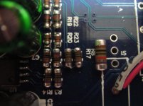
I just take a picture where you can see the 0204 and 0102 soldered in the PCB and near the 0207 as reference.
I hope this can help and I would suggest you to revise also the caps, the ones in BOM not even fit
Best Regards,
Enrico
Attachments
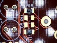
This a view of the PCB manufactured from Bruno's Gerber file, with two size 0805 resistors on it. There is just about enough pad area to solder the components of this size.
Judge by yourself whether you can solder a larger component onto these pads.
Regards,
Braca
Judge by yourself whether you can solder a larger component onto these pads.
Regards,
Braca
Attachments
Thanks Enrico and Braca
Ok, can I suggest to change the BoM as follows:
line 14 - R2 etc.: VISHAY BEYSCHLAG UMB02070G1001BBU00 -> MMU01020E1001BB300
line 19 - R8 etc.: VISHAY BEYSCHLAG UMB02070G1002BBU00 -> MMU01020E1002BB300
line 21 - R19 etc.: VISHAY BEYSCHLAG UMB02070G1002BBU00 -> MMU01020E1002BB300
Regarding the capacitors, the diameter of the proposed ones was too big, right? Assuming from your previous pictures Enrico there's only 5mm diameter per cap, correct? I would not use ELNA SilmicII RFS-25V220ME3#5, since they are only rated 25V whereas Bruno specifies 63V. I'd therefore suggest to change:
line 4 - C10 etc.: ELNA - RFS-100V220MH5#5 -> Nichicon UKW1J220MDD or UFW1J220MDD (don't know how series KW and FW differ?)
line 5 - C12 etc.: ELNA - RFS-25V102MJ8#5 -> Nichicon UKT1E102MPD (these seem to be fine, and with 10mm diameter the smallest possible)
Enrico, why did you change C4 etc.? For technical reasons or to stick with Nishicon also here?
Thanks,
Robert
Enrico, why did you change C4 etc.? For technical reasons or to stick with Nishicon also here?
For the same reason, the ELNA proposed in the BOM are 10mm diameter and doesn't fit. I choose the Nichicon because was the best choice (IMO) that fit in the pcb as they are 6.3mm.
Regards,
Enrico
I see, thanks.
Unfortunately UES1V100MEM is only rated 35V whereas the spec requires 50V, so I'd suggest a further change to the BoM:
line 3 - C4 etc.: ELNA - RBD-50V101M -> Nichicon UVP1H100MED (50V) or UVP1J100MED (63V)
Unfortunately UES1V100MEM is only rated 35V whereas the spec requires 50V, so I'd suggest a further change to the BoM:
line 3 - C4 etc.: ELNA - RBD-50V101M -> Nichicon UVP1H100MED (50V) or UVP1J100MED (63V)
Yes, the pads are all 0805
Was there a reason you chose cylindrical SMD over the 0805 flat types themselves? Or just availability?
No, that's what my research at Mouser came up with given the parameters (MELF in particular)
Last edited:
I had a look at 0.5W 1206 are readily available. 6p more than melf. Unless we need 1W parts in the PSU I would stick with flat for the 2R2?
I definitely remember Bruno saying you need MELF there for increased inrush performance (i.e. not breaking when switched on).
Jan
Jan
1206 smd resistors are generally 1/4W, but they are also available in upto 1W types.
Bonzai specified 1W 1206 for his NX amp.
A 1/2W 1206 2r2 has a continuous current rating of 477mA.
The maximum for a one shot transient will be at least 950mApk.
Is melf much better?
Is the difficulty of handling a round component worth the extra (if needed)?
Bonzai specified 1W 1206 for his NX amp.
A 1/2W 1206 2r2 has a continuous current rating of 477mA.
The maximum for a one shot transient will be at least 950mApk.
Is melf much better?
Is the difficulty of handling a round component worth the extra (if needed)?
The only Melf resistors to be used are R25 to R28 because of the high inrush current at switch on in order to load C12 to C15.
None of the other resistors should be Melf.
The 1K and 10K resistors specified in the Bom by Bruno as "Precision Thin Film" should be 0.1% or better because of their direct impact on CMRR.
These 1K resistors should also have a very low Tempco of 25ppm/C to prevent thermal modulation.
Using 0.1% resistors will give you a CMRR in the order of 60dB.
The remaining resistors are less critical.
Is LM4562 best choice for dc removal (U3) ?
In the current Group Buy BOM, U3 has been changed from a TL072 to an LM4562 because of the higher offset voltage of the former. A problem with LM4562 is that it has a typical bias current of 10nA and a maximum of 72nA at room temperature (the bias current of the TL072 is a negligible 100pA). Similarly, the input offset current has a typical value of 10nA and a maximum of 65nA.
If you are unlucky enough to have a device near the maximum value it will still produce a largish offset voltage error due to the bias currents flowing in R19 and R16 for the inverting input and R7 and R22 for the non-inverting input.
For example, if the input offset current is 60nA (ie 60nA difference between the inverting and non-inverting bias currents), then the resultant input offset voltage is (60nA x (R7 + R22))= 60nA x 22kilohms = 1.34mV. Admittedly this is better than the TL072 typical offset voltage of 3mV (6mV max) but not a lot better. If you a more fortunate and have a "typical" device then the input offset voltage error due to input offset current is only 0.22mV.
In Bruno's circuit U3A has a gain of 10, but the following stage only has a gain of 0.1 giving a overall gain of 1 at the output of U2/U7A. Further gain is applied by U2/7B which is variable due to R5A/B. If we assume a gain of say 2 for this stage then the input offset voltage of U3A will appear as 2 times that value at the final output.
Using an LM4562 for U3 will result in a preamp output voltage of typically 0.44mV (0.22mV x 2) or 2.7mV (1.34 x 2) if your device has 60nA of input offset current.
Using an TL072 for U3 gives a typical preamp output offset voltage of 6mV (3mV x 2) and a worse case of 12mV (6mV x 2).
If your maximum gain is only unity then the above output offset voltages will be halved, similarly, should you use a higher gain, the output offset will increase. Whether these offset voltages are a problem or not is debatable - it depends how much dc you can tolerate sending to your main power amplifier.
A better choice would be a device with low offset voltage and low bias current such as the AD8622 which has a maximum input bias/offset current 200pA and a maximum offset voltage of 125uV or the OPA2277 which has a maximum input offset voltage of 100uV and a maximum input bias/offset current of 2nA. The downside is the higher cost of either of these opamps compared with the very cheap TL072.
regards,
Rick
Rick
The only Melf resistors to be used are R25 to R28 because of the high inrush current at switch on in order to load C12 to C15.
None of the other resistors should be Melf.
The 1K and 10K resistors specified in the Bom by Bruno as "Precision Thin Film" should be 0.1% or better because of their direct impact on CMRR.
These 1K resistors should also have a very low Tempco of 25ppm/C to prevent thermal modulation.
Using 0.1% resistors will give you a CMRR in the order of 60dB.
The remaining resistors are less critical.
Thanks Hans. I will remove the BoM on my website which wrongly specifies lots of melf.
I build up my own unit(s) in the same way as you suggest.
Jan
- Status
- Not open for further replies.
- Home
- Group Buys
- Bruno Putzeys Balanced Preamp - Group Buy