The story goes that Stereophile always uses a 600 ohm resistive source for MM phono amplifier noise measurements and that there is even a Japanese standard prescribing the use of a 600 ohm resistive source. That means that when you design a MM amplifier with a bipolar input stage and you want it to work optimally in real life as well as in measurements, you should really put a switch on it to switch between about 50 uA of input stage collector current for normal use and about 1 mA for Stereophile or Japanese measurements (*) 😱
(*): assuming A-weighting, an hFE of about 600 and counting on a typical cartridge inductance of about 500 mH
(*): assuming A-weighting, an hFE of about 600 and counting on a typical cartridge inductance of about 500 mH
Last edited:
https://www.diyaudio.com/community/attachments/riaapreampschematic-jpg.1038433/Some, in the broadcast industry, like to
?
First stage biased at roughly 35 uA collector current; clearly designed for actual use, not for nonsensical measurements with no source inductance.
Marcel, I'm sure there is a lot of this. The Tek SG505 is a 600 ohm source and it is (or at least was) widely used for audio measurements, including by me. Even leaving cartridges aside, real tuners, preamps, cassette players, CD players, etc., have source Z measured in K, and in the case of valve preamps sometimes hundreds of K.
As I'm sure you know, there is a similar issue when you want to measure the noise level or the sensitivity of a radio: RF equipment invariably has a 50 ohm output impedance while, for example, a passive whip antenna used for medium wave reception isn't even close to 50 ohm. The solution is simple: a dummy antenna, a simple, standardized passive circuit that when connected to a 50 ohm source has an output impedance that is close to that of the real antenna. For passive whip antennas used for AM car radio, the dummy consists of a termination resistor and a 15 pF-60 pF capacitive voltage divider, 15 pF representing the whip antenna and 60 pF the antenna cable.
Similarly, for MM phono amplifiers, the standardization organisations should have defined a dummy cartridge with a big inductance.
Similarly, for MM phono amplifiers, the standardization organisations should have defined a dummy cartridge with a big inductance.
All this nattering about other options for the preamp will fall on deaf ears, as my boards are already finished and stuffed, and should handily out-do any 2-transistor solution, "revered" or no.... The noise observations that originally sparked this thread were made with cartridge in place, which is really how it needs to be done for a practical setup.
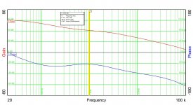
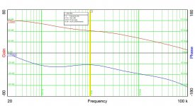
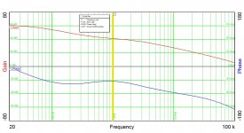
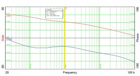
Here's the gain-phase scan from one board, which combines 2 channels of RIAA preamp plus balanceced to unbalanced conversion. The scan is from an unbalanced output used to power an external mixer from its line input.
Attachments

I think I fixed the issues on the other two boards (solder blobs and unsoldered parts). As soon as I'm well and test negative, I'll be running scans on those boards for comparison. Meanwhile, I'm isolating and getting well, albeit somewhat slowly.
Getting better slowly, by stages - it started out rather like one of the more horrible cases of flu I've had.

- Home
- Source & Line
- Analogue Source
- Broadcast RIAA Blues