The combination of AD745, OPA2134, and DRV134 sounded good (enjoyable, actually) in the original incarnation of this preamp. which has soldiered on in our main production studio since the early 2000's. I'm interested in how the combination of OPA227 and TLE2074 will sound. I used what opamps I could find, as there is currently a drought of appropriate through-hole parts (if you don't believe me, check the distributors and see what I mean...). I insist on JFET-input opamps for the preamp first stage because of noise issues due to interaction of the input bias current with the high inductance of MM cartridges. Use of JFET-input parts is also crucial in the feedback scheme I'm using for the basic gain blocks.
The Stanton 680s we originally used in the studios had an inductance of almost a Henry. The Ortofon Pro S cartridges we're currently using have an inductance of about half that (450 mH), so maybe not quite so much of an issue. Keep in mind also that this particular setup doesn't have to be all audiophile nicey-nice, as the signal from the master studio gets considerably mangled in its journey up to the transmitter tower , ~20 miles from the master studio - this is an FM radio station after all, not a living room listening environment. The original caveats on perceived noise with the console slider up still apply. When I can find where I've stashed my AD745s and my OPA4134s, I may swap and see if there is a difference in perceived listenability.
The Stanton 680s we originally used in the studios had an inductance of almost a Henry. The Ortofon Pro S cartridges we're currently using have an inductance of about half that (450 mH), so maybe not quite so much of an issue. Keep in mind also that this particular setup doesn't have to be all audiophile nicey-nice, as the signal from the master studio gets considerably mangled in its journey up to the transmitter tower , ~20 miles from the master studio - this is an FM radio station after all, not a living room listening environment. The original caveats on perceived noise with the console slider up still apply. When I can find where I've stashed my AD745s and my OPA4134s, I may swap and see if there is a difference in perceived listenability.
Last edited:
There are some engineers, who suppose that. For this reason I am looking for commercial RIAA phono stage in this topology.A very long time ago, about 40 years, when I needed to make a RIAA preamp, I was most successful with an inverting amplifier, in spite of the theoretical noise disadvantages. With an inverting amp, any cart impedance improves noise, not increases it, and an open input is dead silent. And there are no headroom issues caused by the EQ curve. In those days, I was using, I think, a 4136, which is a quad 4558 with a strange pin-out. I have to admit that I was not very picky because any phono preamp was going to be noisy. You just need to use the RIAA curve to advantage instead of fighting with it. I had some extra gain with an extra stage, perfect for a quad chip. It was a very long time ago and involved a lot of tweaking, so I don't remember the details.
In this case there is this thread and the URL's from there of interest:
https://www.diyaudio.com/community/...king-in-inverted-mode-not-to-find-why.222677/
P.S.: I don't understand this term: cart impedance
Last edited:
Cartridge impedance. But the point is incorrect, source impedance always turns input current noise into voltage noise, only lower impedances reduce this. However in an inverting circuit the feedback resistor is in parallel with the source (from a noise perspective), and this reduces the effect - making that resistor smaller will reduce noise. Alas it reduces signal as well, so signal/noise ratio is no better, and in fact is worse.
Non-inverting topology always has better noise performance because the signal goes directly to one input transistor without being diluted and without needing any series resistance. The path from transducer to that first input transistor is crucial to noise performance.
Also no system is ever "dead silent" - the noise can always be measured by upping the gain - certainly it can be quiet, but never silent! I built a low-noise test amplifier with ZTX851/ZTX951 and about 10^5-fold gain into headphones - that circuit can allow you to hear the voltage noise difference between a 1 ohm and a 3 ohm metal film resistor, both of which might be thought to be pretty close to silent in most contexts, being 0.13 and 0.22nV/√Hz respectively.
What about this idea ? - found underCartridge impedance. But the point is incorrect, source impedance always turns input current noise into voltage noise, only lower impedances reduce this. However in an inverting circuit the feedback resistor is in parallel with the source (from a noise perspective), and this reduces the effect - making that resistor smaller will reduce noise. Alas it reduces signal as well, so signal/noise ratio is no better, and in fact is worse.
Non-inverting topology always has better noise performance because the signal goes directly to one input transistor without being diluted and without needing any series resistance. The path from transducer to that first input transistor is crucial to noise performance.
Also no system is ever "dead silent" - the noise can always be measured by upping the gain - certainly it can be quiet, but never silent! I built a low-noise test amplifier with ZTX851/ZTX951 and about 10^5-fold gain into headphones - that circuit can allow you to hear the voltage noise difference between a 1 ohm and a 3 ohm metal film resistor, both of which might be thought to be pretty close to silent in most contexts, being 0.13 and 0.22nV/√Hz respectively.
https://web.archive.org/web/20160916041940/http://audioqualia.prophpbb.com/topic60.html
last posting:
Interesting in this system is the presence of a nearly ideal noise reducer which cleans up LP surface noise
along with the preamplifier's input 47kOhm thermal noise.
This circuit is very effective in reducing both vinyl and cassette tape noise, its description and demonstration samples can be found at
https://web.archive.org/web/20160818164201/http://vkaudiotest.co.uk/VK-7 Noise Reducer.htm
As for distortion, the preamplifier and noise reducer guarantee the figures of less than 0,001% within 20Hz-20kHz. However, the main target of audio is the identity of the reproduced sound to its live original.
To Mark - in the original circuit using LT1115 the noise was very obvious and objectionable with the slider up at normal playing level on the mixing console. Substituting a resistor of the same value as the cartridge resistance across the input cleaned up the noise. It was the nearly 1H inductance of the Stanton cartridge that caused the problem. Things quieted down very dramatically after switching to the AD745. I expect similarly quiet operation from the OPA227.
![Img_0027[1].jpg](/community/data/attachments/946/946396-5cc58198bc5bd23a3bf905cf9bbf36f0.jpg?hash=XMWBmLxb0j)
Simpler is not always better - I doubt that 2-transistor design has enough open loop gain to get things right.
Doubts..... hmm.Simpler is not always better - I doubt that 2-transistor design has enough open loop gain to get things right.
If that's the case, then how come just about every manufacturer used that type of design for so many decades?
And satisfied millions of people....
Certainly no doubt about that.
Closed loop gain is near 16 (24dB) at 1KHz, so may be correct, but gain too low for many domestic systems. A radio console tends to have more gain in reserve.I doubt that 2-transistor design has enough open loop gain
True.Closed loop gain is near 16 (24dB) at 1KHz, so may be correct, but gain too low for many domestic systems. A radio console tends to have more gain in reserve.
However, for domestic uses, reducing R3, and perhaps tweaking the feedback values accordingly will bring up gain to anything you want.
With low-noise transistors its quite competent for the masses.
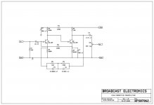
As the gain is increased, the maximum signal before clipping reduces. We can roughly analyze the headroom of the preamp to determine if it is an issue.
The RMS output voltage of moving magnet cartridges is specified at 1 kHz and 5cm/sec. Stanton cartridges output between 4 and 6 mV RMS. Shure cartridges range from 3.2 mV (V15 type V) to 6 mV (M33).
A study of peak levels on records found that 25cm/sec is the limit at 1 kHz. So a cartridge output can be as high as 30 mv RMS.
The Broadcast Preamp is capable of about 2V RMS output according to a LTSpice analysis. If the gain is set to 40dB, a common value for home preamps, a 30 mV input would produce a 3 volt output. This is well beyond the capability of the preamp. At 36dB gain there would be zero headroom for the preamp. Gain reduction below 36dB would begin to provide some headroom.
I have not tried to analyze the noise performance of the preamp but there are several high value resistors in the circuit which might increase output noise.
That 2Tr preamp could be modified as well.
Adding another gain stage like an emitter follower stage would bring up gain.
Adding another gain stage like an emitter follower stage would bring up gain.
OMG! You may be right! I thot 18V could support 5Vrms (barely), but the 18k DC load against two 10k AC loads (10k pot, and NFB 10K @ 1kHz) drag it down.capable of about 2V RMS output
It's for a console with -20dBm (0.077V) native sensitivity. That lines-up almost exact with 5mV and gain of 16. If all your wax is hot, you can trim.
You guys can ague the relative merits of that POS 2-transistor RIAA circuit as much as you like. I'm not going to tear up what I've already done. The circuit in question must also provide balanced outputs to feed our mixing board, as well as unbalanced outputs so that a visiting DJ can plug in his mixing board for things like beat matching. The circuit should also at least make a college try at duplicating the RIAA EQ curve with minimal error, though I will add in some low frequency roll-off, so that signals from warped records don't get in to confuse the downstream signal processing. That 2-transistor circuit is nothing that I would want to leave behind as a legacy with my name attached to it. The same goes for its vacuum tube brother using 12AX7.
I certainly did not recommend the two transistor circuit. It has poor headroom, is not particularly accurate to the RIAA curve, and may be noisy. There is almost no flexibility to improve the circuit with just component value changes. A redesign would be needed. We did kinda hijack your thread and I apologize for that.
We both know who was to blame for that.... What I built for the master studio is very similar to the preamp I built for the KFJC production studio, a design that has served very adequately since 2004. The only service I expect to perform on that older preamp may be a simple re-cap,. Having said that, I used long life low ESR capacitors (Panasonic HFQ) for PS filtering, so they may still be good...
How about the UREI 1122 phono preamp, allegedly found in many recording studios and radio stations. It has balanced outputs... but uses a mere two transistor RIAA stage, LM301 with MPSU55/MPSU05 booster for line driver, and an unregulated power supply. 0.5% THD, 60 dB hum and noise, and 42 to 50 dB channel separation. The "response trimmers" look an awful lot like tone controls. It's disturbing how much people are willing to pay for these.

The 1622 card from the revered 1620 mixer looks better; sometime this century I hope to build a version.

Schematics stolen from:
http://www.davegroupjapan.com/ekoukoku13.html
The 1622 card from the revered 1620 mixer looks better; sometime this century I hope to build a version.
Schematics stolen from:
http://www.davegroupjapan.com/ekoukoku13.html
Last edited:
To Mark - in the original circuit using LT1115 the noise was very obvious and objectionable with the slider up at normal playing level on the mixing console. Substituting a resistor of the same value as the cartridge resistance across the input cleaned up the noise. It was the nearly 1H inductance of the Stanton cartridge that caused the problem. Things quieted down very dramatically after switching to the AD745. I expect similarly quiet operation from the OPA227.
It's interesting that you managed to get so far from the noise optimum that it was audible and even objectionable with a record playing. Underestimating the effect of the equivalent input current noise is a very common mistake, even Douglas Self made it in the mid-1990's, but often record surface noise still masks things when there is a record playing.
See https://worldradiohistory.com/UK/Wireless-World/00s/Electronics-World-2003-10-S-OCR.pdf pages 38...43 for a simple way to account for the frequency-dependent cartridge impedance. Mind you, one section of the switch in figure 5 is drawn in the wrong position and the terms spectral density and power spectral density are mixed up. 3852 Hz becomes 5179 Hz when you use ITU-R 468- instead of A-weighting.
The LT1115 and LT1028 are really the very worst op-amps for MM amplifiers. The only thing that's even worse is several of them in parallel, as Elektor used in the MM version of the Supra 2.0. That reduces the already negligible noise voltage, but makes the noise current even worse.

- Home
- Source & Line
- Analogue Source
- Broadcast RIAA Blues