At first glance, that seems to work too. Nice!How about correcting the current at the source ?
Mona
Also currents could be joined at the drains.
That will definitely not work... think it through and you will see why.
The resistor bridges R12--14 / R28--31 creating the injection nodes a b c d will degrade the open loop gain, as the signals from the input diffs runs through these now 'semidiffs' and add some signal of opposite phase into the opposite outputs of the input diffs. This is unavoidable because of the neccessary CMctrl injection in top and bottom current mirrors.
Here is another way. This method does not have the pointed out issue which is not an issue 🙂.
Attachments
That will definitely not work... think it through and you will see why.
Already, but it was attractive.
What about attached?
Attachments
That will work, remove Q7, Q4 and short Q1 and Q5 collectors to supplies.
Here, you have now moved to a folded cascode topology over mirrors, which is absolutely fine.
Take a look at post #43 is you want to stick with mirrors.
Here, you have now moved to a folded cascode topology over mirrors, which is absolutely fine.
Take a look at post #43 is you want to stick with mirrors.
Last edited:
Here, you have now moved to a folded cascode topology over mirrors, which is absolutely fine.
😉
Take a look at post #43 is you want to stick with mirrors.
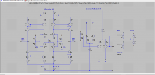
With common-mode tracking current sources at a folded cascode sources we're at the place where two LTPs are opposing each other in a super-symmetrical manner.
But while first LTPs(or self-biased JFET stage) are rejecting common mode itself the second stage are keeping otputs referred to supply's centertap.
So common mode noise are effectively rejected from signal and signal itself are effectively referenced to amp's supply centertap.
Perfect.
What do you think, are we need to have second gain stage or we can leave just one folded cascode stage for simplicity?
Last edited:
With common-mode tracking current sources at a folded cascode sources we're at the place where two LTPs are opposing each other in a super-symmetrical manner.
That was still the case with mirrors... but yet again, nothing wrong with a folded cascode approach.
What do you think, are we need to have second gain stage or we can leave just one folded cascode stage for simplicity?
In my opnion, a single gain stage design like this one is not adequate. For a good audio amplifier, IMO you need a two stage design + an output stage. Adding a second gain stage to this topology will be tricky since the outputs of the first stage are now referred to mid-supply and not a power rail like in the traditional designs.
How you plan to do this will be a learning excercise for you (I know how to do it if you get stuck though). Hint, think of the AD844.
FYI, in case there is a doubt, a cascode is not a gain stage... it is just a current conveyor or current buffer.
Best, Sandro
In my opnion, a single gain stage design like this one is not adequate. For a good audio amplifier, IMO you need a two stage design + an output stage. Adding a second gain stage to this topology will be tricky since the outputs of the first stage are now referred to mid-supply and not a power rail like in the traditional designs.
How you plan to do this will be a learning excercise for you (I know how to do it if you get stuck though). Hint, think of the AD844.
Of course, Voltage-to-Current-to-Voltage-to-Current-to-Voltage chain.
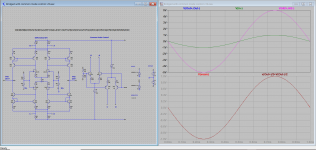
Now i need to curb with this gain niagara falls...
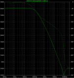
Attached, OLG still uncompensated, but shows achieved.
Yes, but its output is a Hi-Z node, so current can be converted back to voltage and both with load it becomes a Hi-Zout voltage gain cell.FYI, in case there is a doubt, a cascode is not a gain stage... it is just a current conveyor or current buffer.
Attachments
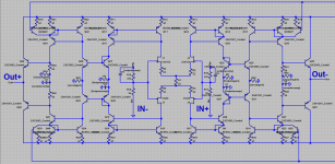
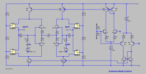
Just to make sure we are on the same page, how many gain stages do you have per side (i.e. on the plus side and on the negative side) on your new schematic (#48)?
I see two per side, on the OUT+ side: first stage from IN- to R9||C2, second from R9||C2 to R44||C3.
The last bit of the chain is OPS (R49, R50, Q46, Q48).
Now... see if you can compensate it. As is, you will run into a problem. Think of the polarity of the 2nd gain stage (from R9||C2 to R44||C3), is it inverting or non-inverting?
Also, as drawn your CM control won't work. I already showed you 2 ways to do it properly with current mirrors.
Nice progress, Sandro
A first (safe) zero is prominent at 100Khz, kicking in from 10kHz onwards, a second hidden in a two pole compound way above 10M, but these poles give rise to surprising side effects nonetheless. Kill this bode plot above 10k please in any matter. Things and reality goes beserk.
- Home
- Amplifiers
- Solid State
- Bridged topology with common-mode control