Has anyone bridged the LM3886 using the schematic here :-
http://www.national.com/an/AN/AN-1192.pdf
The "out" uses pin 3 of each chip, and not pin 3 +grd. It seems that the circuit incorporates a Zobel network, but not in the same way as here:-
http://myweb.tiscali.co.uk/nuukspot/decdun/gainclone_3886.html
It all works o.k and Dc offset is 0.07mv.
Any thoughts anyone ?
I have finished the amps and added a Zobel network (even if one already exists) and they sound fine to me.
I was wondering whether the power requirements in bridged mode were the same as for a single chip. I am currently using a 25v ac tranny which after rectification gives 32 volts per rail. The data sheet says that the max per rail is 35vdc. However it says the max it can take is 84vdc, which would suggest 42vdc per rail.
I have a 30vac tranny and wondered if it was safe to use. The chipamp.com site says that people have used 30v trannys with their kits with success ?
Hi,
+-32Vdc used as a supply voltage requires approximately 6.5ohm load impedance to hit the maximum 60W capability of a single chipamp. page14: graph Output Power vs Supply Voltage (from the October 2003 datasheet).
When in bridged mode this limits the load to about 13ohms due to the standard rule of double the power into double the load, i.e. 60W into 6r5 becomes 120W into 13r.
From the same graph, you can extract the maximum supply voltage to drive 60W into 4r0 and use this supply voltage for a bridged amp.
i.e. +-26Vdc gives 120W into 8r0.
All the above data assumes a perfect PSU whose voltage does not vary with changes in load power.
If you assume that the supply voltage will sag on sustained power (bass notes) then the quiescent voltage can be higher. Transient output voltage will now be dependant on the quiescent supply voltage and higher peak voltages and peak currents will be available. If any of these peaks are prolonged and exceed the preset IV & temp capability then Spike should step in to protect the chip.
So it now comes down to how quickly the supply sags and how far it sags when asked to deliver significant power.
using +-32Vdc and finding that it sags to +-26Vdc when driving 4r0 to 120W just keeps each chipamp within that 60W limit.
It's a case of measuring what you have and making a reliability/lifetime choice.
Hi Andrew, Thanks for the reply.
You may be able to answer this. When I was testing the amps with a "lightbulb" lead, when I turned the volume up high,the bulb would glow and pulse in time with the music, could this be beause the power supply was sagging, or that the VA rating of the tranny (160VA) is too small ?
Rob.
You may be able to answer this. When I was testing the amps with a "lightbulb" lead, when I turned the volume up high,the bulb would glow and pulse in time with the music, could this be beause the power supply was sagging, or that the VA rating of the tranny (160VA) is too small ?
Rob.
It's normal for that to happen. The light bulb is really just a visual indicator of the power being drawn by the amp (and a crude but neat current limiter).
The basic concept is that if the amp were drawing 100W of power (50W in to the load at 50% efficiency?!) and you had a 100W light bulb, the bulb would be lit brightly. It would also limit the amount of power the amp can draw to 100W ish.
When playing music the light bulb will glow with the music, mostly when the bass hits, as more power is being drawn by the amp / delivered to the speaker.
You may find that your power supply rails are slightly lower with the light bulb there, and you'll probably also experience much more sag under load, but it isn't really an indicator of either of these conditions.
markiemrboo. Thanks for that. However I would still like to know if my tranny could do with more VA ?
How much voltage sag occurs with your present VA transformer?
try measuring both Vout and Vsupply for :-
open circuit no signal
open circuit driven to just below clipping
16ohm driven to just below clipping
8ohm driven to just below clipping
4ohm driven to just below clipping.
A good amp will have an output voltage that drops by no more than 1dbV for this range of tests.
A very good amp <=0.5dbV
But, all the test measurements must be done with the mains voltage at the same nominal value.
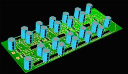
This is my version of the bridged/parallel LM3886. I will have boards in the next few days. It is for sub use and should push 600W @ 2 ohm. I will use it at lower voltage and 4 ohm load for about 350w output.
The short chips along the edge are the LM3886's. I haven't updated the rendering model to show it accuratly.
The short chips along the edge are the LM3886's. I haven't updated the rendering model to show it accuratly.
Attachments
Originally posted by Puffin
I have a 30vac tranny and wondered if it was safe to use. The chipamp.com site says that people have used 30v trannys with their kits with success ?
30 Vac means 42.5 Vdc at each rail? This is very high for a normal gainclone despite it might work and sound nice, but you NEVER should power a bridged gainclone from this power because the amplifier already sees a harder load (4 Ohms instead of 8). Bridged gainclones on 8 Ohms should be thinked as if they were standard gainclones in 4 Ohms ad thus operated from lower power supplies (25Vdc is OK, don't go higher).
you are kidding yourself.InlineTwin said:This is my version of the bridged/parallel LM3886. I will have boards in the next few days. It is for sub use and should push 600W @ 2 ohm. I will use it at lower voltage and 4 ohm load for about 350w output.
The short chips along the edge are the LM3886's.
350W into 4r0 requires 52.9Vpk =37.4Vac into your load and require upto 12.6Apk from each of a three parallel pairs set up (6 chipamps in bridged/parallel).
Do you really expect the chipamps to survive supply rail voltages of around +-57Vdc? You seem to be ignoring the maximum current specification of 7 to 11Apk.
In DIY, you either slavishly copy a good working design or you learn to do some of the arithmetic. Spouting impossible numbers does not achieve anything. As for 600W into 2ohm, you are in the dream world of car audio fiction.
AndrewT said:the dream world of car audio fiction
Andrew , someone should write a book with that title!!!
I would buy it.
so that you can try to understand what is or isn't inside their heads?tangmonster said:New book title
"the dream world of car audio fiction"
Andrew, someone should write a book with that title!!!
I would buy it.
AndrewT. I haven't had a chance to do the tests you suggested in post 7, but I will do and report back. I see from the post from ionolo that when bridging, the chips are seeing 4ohms and 25vdc is all that is required (presumably it doesn't matter whether your speakers are 8 or 4ohm speakers?)
I assume that if I was running 4ohm speakers that You would get more power.
I assume that if I was running 4ohm speakers that You would get more power.
no, bridged into 4ohms=more smoke.Puffin said:I see from the post from ionolo that when bridging, the chips are seeing 4ohms and 25vdc is all that is required (presumably it doesn't matter whether your speakers are 8 or 4ohm speakers?)
I assume that if I was running 4ohm speakers that You would get more power.
Each channel in a bridged amp sees only half the load impedance at the output terminals.
Bridging into a 4ohm load is equivalent to driving a 2ohm with a single channel.
The standard rule for bridging is:- twice the power into twice the impedance.
AndrewT said:so that you can try to understand what is or isn't inside their heads?
The book could go in any direction.
Into a commercial (make sell stuff with slogans) journey.
Into a "How stupid can people be" journey.
A How Lazy our minds have become in the age of computers that nothing is based on calculated truths anymore.
It can be about stupid consumers who believes anything they read.
I am listening to very calm music at the moment , thinking too deep. I'll rather get back to work ,have to help troubleshoot a few of our company's pc boards that are fresh from the population house.
Working probably is "better" than going off topic in a diy audio forum.
AndrewT said:you are kidding yourself.
350W into 4r0 requires 52.9Vpk =37.4Vac into your load and require upto 12.6Apk from each of a three parallel pairs set up (6 chipamps in bridged/parallel).
Do you really expect the chipamps to survive supply rail voltages of around +-57Vdc? You seem to be ignoring the maximum current specification of 7 to 11Apk.
In DIY, you either slavishly copy a good working design or you learn to do some of the arithmetic. Spouting impossible numbers does not achieve anything. As for 600W into 2ohm, you are in the dream world of car audio fiction.
Did you not look at the layout??? It is 12 (that's twelve) LM3886 in BRP. Don't start spouting off nonsense when you have not reviewed the project.
Read section 4.5 in the AN-1192. It gives Pd max, which gives the max disspiation allowed on each chip in the BRP configuration. You can back out a voltage from this and I think you know where to take it from there to find max power out.
As an example to make sure you are doing it right try to get the 200w number they show at 8 ohms and +-37 volts. Maybe you will surprise yourself.
As an example to make sure you are doing it right try to get the 200w number they show at 8 ohms and +-37 volts. Maybe you will surprise yourself.
I missed 6 of the chipamps.InlineTwin said:It is 12 (that's twelve) LM3886 in BRP.
But, I stand by the impossible peak voltages shown in my example calculation. The current/chip would be halved using 12 rather than 6chipamps.
Your project still cannot achieve 350W into 4ohms nor 600W into 2ohms.
- Status
- Not open for further replies.
- Home
- Amplifiers
- Chip Amps
- Bridged LM3886 (again ?)