Bridge of Zen problem
Hello, I began to built the Power supply of the bridge of Zen today and I have problem !!!
At the output of the power suppluy, I have only 47 V !!!!!
At the output of the bridge, I have 93 V !!! I have 69V AC at the output of the transformer, , more than on the shema but the output of the power supply is "unload"
I use the TIP29CFS of DIGIKEY.... maybe it is not the same of TIP29CGE ???
At the base of the TIP29, I have 47 V.... I suppose to have 60....
At the collector, I have 93v
At the emitter, I have 60 v
I need some help !!!! I don't know the problem !!!!
thank you very much !!!
Hi, I built several weeks ago a "Bride of Zen" preamp. You can take a look a my thread:
http://www.diyaudio.com/forums/showthread.php?s=&threadid=13570
Since TIP29CFS is obsolete, yes, you can replace those by TIP29CGE.
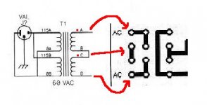
Concerning you power supply problem, please verify that your transformer's secondarie are correctly connected (Attention to phase, generally identified by a dot). Also, check diodes polarity. I don't know if you're using P2P or PCB technique but if you're using PCB, make sure that your supply wiring looks like this :
I hope this helps
http://www.diyaudio.com/forums/showthread.php?s=&threadid=13570
I use the TIP29CFS of DIGIKEY.... maybe it is not the same of TIP29CGE ???
Since TIP29CFS is obsolete, yes, you can replace those by TIP29CGE.
Concerning you power supply problem, please verify that your transformer's secondarie are correctly connected (Attention to phase, generally identified by a dot). Also, check diodes polarity. I don't know if you're using P2P or PCB technique but if you're using PCB, make sure that your supply wiring looks like this :
I hope this helps
Attachments
no, it is not a wiring problem because I have 93 v at the output of the bridge.....
Somabody can say me if the Voltage on my TIP29 is normal ????
Somabody can say me if the Voltage on my TIP29 is normal ????
Yes, if you have 47V at the base of the tip, you will see a little less than 47V at the output of the power supply. This only means your PS is working. If you want 60V instead of 47V you have to check the zehner diode chain. at the point between the zehners and R1, at the base, you need 60,6V. Maybe you mounted a zehner wrong way, or it is defective. Use a Voltmeter and measure beween every zehner diode in the chain. What voltages do you read?
The zener are OK because I have 60 V at the emitter, across C2 !!!!
and I have 33V across R1 ..... 93-60=33
The probleme is not the zener !!!
Maybe, the TIP29 is broken by the static ????
and I have 33V across R1 ..... 93-60=33
The probleme is not the zener !!!
Maybe, the TIP29 is broken by the static ????
In case you have 60V at the emitter you have 60V at the output of the powersupply. And at the emitter is NOT across C2. across C2 is the base, and in case you have 60V at the base you should have 59,4V at the emitter with a right mounted and not blown TIP29.
I propose you download a datasheet of the transistor and take a look which pin is base, emitter and collector, and check your wireing.
http://www.google.de/search?hl=de&lr=&ie=UTF-8&oe=UTF-8&q=tip29+datasheet&spell=1
From what you tell i feel you mixed up the pis and mounted the transistor wrong way.
http://www.elektronik-kompendium.de/sites/bau/schalt/02012911.gif
It helps to look at the pinout before soldering. It helps to look here http://www.passdiy.com/pdf/brideofzen.pdf
how the device should be connected.
good luck!
Thank you very much..... I inverted the collector with the emitter !!!
Now, I have 59,5 V at the output !!! thank you for your help !!!
I have an other question, I just want to know if the 93V on C1 is a problem, I use a 1000uf 100V by ELNA ???
thank you again !!!!
Now, I have 59,5 V at the output !!! thank you for your help !!!
I have an other question, I just want to know if the 93V on C1 is a problem, I use a 1000uf 100V by ELNA ???
thank you again !!!!
You are not the first who did this....much..... I inverted the collector with the emitter !!!
If you do a search some people in this board say they prefer to use elkos rated at 20 to 100% over the voltage they apply to it. I have no problems using it at the limit, 93V is < 100V so it should work.
Idon't want to have the same problem with the Mosfet IRF610
I look at the data sheet and I don't see what is the GATE pin, or DRAIN pin or Source pins......
anybody know what is the first, second and last pin on the IRF610 ???
I look at the data sheet and I don't see what is the GATE pin, or DRAIN pin or Source pins......
anybody know what is the first, second and last pin on the IRF610 ???
Thank you very much !!!!
For the 5K Pot at the output...... when the pot is at 5 k , the "volume" is at the max and when it is at 0 ohm, the "volume" is close ???
For the 5K Pot at the output...... when the pot is at 5 k , the "volume" is at the max and when it is at 0 ohm, the "volume" is close ???
Hi, I just recently became a proud "father" of boz. It is working great, but I just tested it with a discman as input, Marantz 2020 (old 20W reciever) on the output, and bad cables (some speaker wire was laying around, and I didn't buy shielded cable). So, when I play music it sounds good (as bad as discman😉, but I hear a slight hum. I didn't connect all the GND's to mains ground. Can you tell me how to get rid of the humm? I have 3.91V across R104 which is 1.2 kohm (should I lover it down to,say 820?).
I need some help please !!!
At the output of the power supply of my Bridge of Zen, I have 60 V, but when I connect it to the circuit, it drop to 28 V.
Can you help me, I don't understand....
I tried it with no cd player and with no amplifier....
At the output of the power supply of my Bridge of Zen, I have 60 V, but when I connect it to the circuit, it drop to 28 V.
Can you help me, I don't understand....
I tried it with no cd player and with no amplifier....
- make sure you wired the circuit correctly and with right values.
- did you use the Tip29 you allready smoked halfway? try a new one?
- what kind of transformer do you use?
- R104 1kOhm or less? what happens with only this resistor connected to the power supply (between GND and the TIP29?
- What value is R1?
- Did you use larger value than 47,5 Ohm for R2 and R3 ?
- Yes I use the same tip29 but I have 60 V at the outputwithout load
- I use a 120 VA transfo by Plitron 30v-30v
- R104 is 1K
-R1 is 4,75k
-R2 and R3 are 47,5 k
- I use a 120 VA transfo by Plitron 30v-30v
- R104 is 1K
-R1 is 4,75k
-R2 and R3 are 47,5 k
R2 and R3 need to be 47,5 Ohm, or nothing (0R) or something small lets say below 100R or so. Not kOhms.
If you leave them away and still to less voltage, use another TIP.
If you leave them away and still to less voltage, use another TIP.
If you let them out there will be no connection/ no current may flow. You need to substitute them by a piece of wire, a 0Ohm resistor, short them with a cable etc. You don´t need them for funktion. The provide filtering for better power supply / clean voltage.
Better first you tell me: are they 47.5 R or 47,5 kOhm ??? And do you have 47,5 R on hand or not? if not and they are 47,5k , short them.
And be sure you wired the circuit correctly!
what happens now?
Better first you tell me: are they 47.5 R or 47,5 kOhm ??? And do you have 47,5 R on hand or not? if not and they are 47,5k , short them.
And be sure you wired the circuit correctly!
what happens now?
- Status
- Not open for further replies.
- Home
- Amplifiers
- Pass Labs
- Bride of Zen problem