Can this be done:
I have a transformer with just one 12.6V winding. I really want the first stage's heater supply to be DC (6.3V) for noise reasons. The second stage (2x ECC99 PP) draws so much current that regulating is impractical and AC is fine there anyway. Is it possible to properly use one winding for both regulated DC and AC?? How about ground reference. Charging peaks etc.
I have a transformer with just one 12.6V winding. I really want the first stage's heater supply to be DC (6.3V) for noise reasons. The second stage (2x ECC99 PP) draws so much current that regulating is impractical and AC is fine there anyway. Is it possible to properly use one winding for both regulated DC and AC?? How about ground reference. Charging peaks etc.
how much current you want on the 6.3V filament?
LM317 constant current source from rectified and filtered 12.6
all floating, may be a problem if the 1st stage is a rectifier at B+
LM317 constant current source from rectified and filtered 12.6
all floating, may be a problem if the 1st stage is a rectifier at B+
Last edited:
Reading black my own post, I probably should have mentioned that the transformer only has one heater winding. There's one for B+ as well.
I need 6.3V @ 300mA DC and 12.6V @ 800mA AC from the same winding.
I need 6.3V @ 300mA DC and 12.6V @ 800mA AC from the same winding.
rectify 12.6 either full or half wave and run a LM317 and 4.7 ohm to set a constant 270 mA into the 6.3 filament, heat sink on LM317.
A linear regulator would indeed waste a lot of the available power.
Why not try a buck regulator which would be much more efficient.
Why not try a buck regulator which would be much more efficient.
yes tubes waste a lot of heat too ,
I'd imagine trying save power, little here and there isn't their priority esp if quiet DC filament power.
I'd imagine trying save power, little here and there isn't their priority esp if quiet DC filament power.
rectify 12.6 either full or half wave and run a LM317 and 4.7 ohm to set a constant 270 mA into the 6.3 filament, heat sink on LM317.
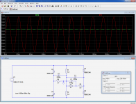
Yes, that's what I did. And I tied the DC 0V line to the GND of the rest of the circuit for reference. But I'm getting a lot of 50Hz interference and suspect the culprit being the unbalanced AC heater wiring. The AC before the rectifier is no longer a nice sine wave and I don't see a way to balance/ reference it.
Buck SMPS is a bit out of my comfort zone at the moment 😱
cant you float the whole filament string and run the LM317 straight from 12.6 using full wave and a tiny cap for lower distortion?
using half wave cuts one side of the sine trading distortion for a just a little power saving. so bad for balance. full wave use a very small filter cap and a little series R
using half wave cuts one side of the sine trading distortion for a just a little power saving. so bad for balance. full wave use a very small filter cap and a little series R
Last edited:
Here is a "creative" solution: it is not too wasteful, it remains balanced, and all filaments share a common that may be grounded if desired.Yes, that's what I did. And I tied the DC 0V line to the GND of the rest of the circuit for reference. But I'm getting a lot of 50Hz interference and suspect the culprit being the unbalanced AC heater wiring. The AC before the rectifier is no longer a nice sine wave and I don't see a way to balance/ reference it.
Buck SMPS is a bit out of my comfort zone at the moment 😱
I assume the 12.6V filaments F1, F2 have a CT.
F3 is the 6.3V 300mA filament. The current can be fine-tuned with R5.
R4 is a dummy load, required to rebalance the bridge formed by the two high current filament.
The dissipation is the same as in the low-power filament, which is still tolerable
Attachments
Last edited:
Difficult. You somehow have to stop rectifier hash, charging pulses etc. from the DC supply getting onto the AC supply for the ECC99 - because this noise will be worse than simple AC.
Does the 12.6V winding have a CT? If so, it can be done by producing a bipolar DC supply (e.g. +-8Vish after rectification and smoothing) with the CT grounded.
Does the 12.6V winding have a CT? If so, it can be done by producing a bipolar DC supply (e.g. +-8Vish after rectification and smoothing) with the CT grounded.

Did you try with using just AC powered heaters for starters, with one heater end of input valve grounded (ie. no humdinger) and a dropper resistor at the other end of that heater, and compared the noise/hum performance against exactly the same circuit setup but with a 6V battery powering the input valve. My concern is that you are attempting to stop a problem that isn't there is the first place, and inserting a 'solution' that is digging a bigger hole for you.
Another heater arrangement would be to use dropping resistors on each end of the input valve heater, and to use a humdinger pot with wiper to ground to tune out heater induced hum from the input valve.
Of course this assumes you have also done all the standard AC hum reduction techniques, such as wire routing and spigot grounding.
Ciao, Tim
Wow, lot's of input. Thanks!
Exactly! The AC becomes so f'd up, I tend to think the interference is I'm hearing is at least partly caused by this. Plus the inability to connect a humdinger between the AC leads (because the DC part is already grounded). worsens this effect. The transformer doesn't have a CT, so that's not an option.
Difficult. You somehow have to stop rectifier hash, charging pulses etc. from the DC supply getting onto the AC supply for the ECC99 - because this noise will be worse than simple AC.
Does the 12.6V winding have a CT? If so, it can be done by producing a bipolar DC supply (e.g. +-8Vish after rectification and smoothing) with the CT grounded.
Exactly! The AC becomes so f'd up, I tend to think the interference is I'm hearing is at least partly caused by this. Plus the inability to connect a humdinger between the AC leads (because the DC part is already grounded). worsens this effect. The transformer doesn't have a CT, so that's not an option.
How do you come up with this stuff! I'll breadboard the whole thing and report back.This variant reduces the peak currents in the windings:
Well, I've experimented a lot with heater arrangements a couple of years ago (although I wasn't confronted with my current issue back then) and have somewhat settled with DC for at least the first stage ever since. So I haven't considered using AC for the first stage. Maybe tome to revisit 🙂. I don't quite follow the suggested arrangements with partly grounded heaters etc. and I'm not familiar with spigot grounding.Did you try with using just AC powered heaters for starters, with one heater end of input valve grounded (ie. no humdinger) and a dropper resistor at the other end of that heater, and compared the noise/hum performance against exactly the same circuit setup but with a 6V battery powering the input valve. My concern is that you are attempting to stop a problem that isn't there is the first place, and inserting a 'solution' that is digging a bigger hole for you.
Another heater arrangement would be to use dropping resistors on each end of the input valve heater, and to use a humdinger pot with wiper to ground to tune out heater induced hum from the input valve.
Of course this assumes you have also done all the standard AC hum reduction techniques, such as wire routing and spigot grounding.
Ciao, Tim
Can you not put the heater windings in series.
All-in-all you want a full wave bridge and a decent cap to maximise the power available to you from the transformer. Then you want to minimise the loss through a regulator to the heater windings. In order to make the linear regulator as efficient as possible you want maximum voltage at minimum current.
All-in-all you want a full wave bridge and a decent cap to maximise the power available to you from the transformer. Then you want to minimise the loss through a regulator to the heater windings. In order to make the linear regulator as efficient as possible you want maximum voltage at minimum current.
It is only phono and mike preamps which benefit from DC heaters for the first stage. Almost everything else is fine with AC - until cheap semiconductor rectifiers arrived there was no other choice. You need tight twisting, run right next to the chassis (in a corner if possible), and only untwist right at the valveholder tags so that the unavoidable loop is as small as possible. Look in any valve era book for details.
Use thin wire for the first stage heater, then you can get a tight twist. This wire should only carry current for the first heater. Later stages can use slightly thicker wire.
The centre spigot found in most valveholders should be grounded - either signal ground or safety ground, whichever is most convenient. If you use signal ground for this then you can use the spigot as a local star point.
Can you not put the heater windings in series.
All-in-all you want a full wave bridge and a decent cap to maximise the power available to you from the transformer. Then you want to minimise the loss through a regulator to the heater windings. In order to make the linear regulator as efficient as possible you want maximum voltage at minimum current.
There's just one I'm afraid. 25.2V would indeed make life a lot easier.
Suggested configuration of input stage heater so it is symmetric around 12.6VAC midpoint, and using a humdinger pot to tune out any residual AC coupling asymmetry to input grid.
Suggested configuration of input stage heater so it is symmetric around 12.6VAC midpoint, and using a humdinger pot to tune out any residual AC coupling asymmetry to input grid.
Thanks! A picture says more than... Good arrangement to combine 6.3AC and 12.6AC and still balance them.
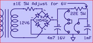
A simple way to do it is like this.
The resistor "1E 5W" (1 ohm) depends on the (unnown) losses in the transfo and diodes.
Mona
Ah, a DC option, without the use of a regulator. That would resolve the issue with high current demands etc.
I like Ketje's solution. You could also use a choke in place of that 1E resistor. Bulky, expensive but it would keep your sine waves nice and smooth and would not get hot.
Sent from my iPhone using Tapatalk
Sent from my iPhone using Tapatalk
- Status
- Not open for further replies.
- Home
- Amplifiers
- Power Supplies
- Breaking my head over AC+DC heater reference