Hi Guys!
I use my DH-101 to connect my iPod, computer and other line level devices. I DO NOT use the phono inputs and I don't ever plan to.
Could you circle the phono sections (probably easier to do on the board layout, and not the board photo) and also what things I could (if I should bother) to remove so the phono preamp section no longer is part of the preamp? I ask as I'm going to replace the resistors with 1% metal film ones, and only want to replace the resistors in the line level, tone, and output circuitry.
Also, do you guys know a source for replacement push button switches and pots (volume/balance pot might be impossible) I don't need a new volume pot or pushbutton switches, but I do have to clean the switches ofter, and the pots about twice a year (I use DeOxit) and it can be a hassle.
Lastly, if these push button switches become too much of a hassle, I can use an external source selector. But after the inputs go to their switches, it ends up going to the main "line in" on the PC-4 board and from there you can adjust the tone, vol, val, etc. What eyelets are those? I have a hard time following the schematic, and the fact that it spans two pages and isn't neat due to the photo copy doesn't help. 🙂
Thanks,
-Nick
DH-101 Schematic
Attachments
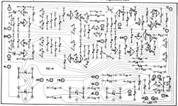
This thread looks familiar. Now that I understand what you want to do, and can almost understand the schematic, can maybe help. The eyelets are marked in the schematic as small circles with an x in the center. Both phono inputs go to the first set of switches, then to eyelets 1 and 2 of the pc-4 (left is 1l and2l, right is 1r and 2r. Eyelet 1 is the signal 2 is the ground. The output of the phono preamp is (this is missing in my copy which is probably the same as you have) are eyelets 3l and 3r. Simple way to bypass phono preamp would be to disconnect eyelets 1 and 3 from each respective channel, and connect them together. Resistor components for tone and high level can be determined from the schematic.
Hi,
Removing R2, R3, R4, R5, R10, R11 will disconnect all sections of
of the phono preamplifier from the power supply. Resistors up to
R15 are part of the phono preamplifier, update R16 and above.
rgds, sreten.
Removing R2, R3, R4, R5, R10, R11 will disconnect all sections of
of the phono preamplifier from the power supply. Resistors up to
R15 are part of the phono preamplifier, update R16 and above.
rgds, sreten.
This thread looks familiar. Now that I understand what you want to do, and can almost understand the schematic, can maybe help. The eyelets are marked in the schematic as small circles with an x in the center. Both phono inputs go to the first set of switches, then to eyelets 1 and 2 of the pc-4 (left is 1l and2l, right is 1r and 2r. Eyelet 1 is the signal 2 is the ground. The output of the phono preamp is (this is missing in my copy which is probably the same as you have) are eyelets 3l and 3r. Simple way to bypass phono preamp would be to disconnect eyelets 1 and 3 from each respective channel, and connect them together. Resistor components for tone and high level can be determined from the schematic.
Yup it is. I asked on AK and diyaudio. Different people on the forums.
Main line in would be eyelets 4l and 4r next to the balance/volume pots on the board.
Ahh. For some reason I was thinking connecting stuff to the PATCH input would bypass volume and tone controls. Schematic begs to differ.
I don't need to remove the phono section, and probably won't. but I want to isolate it and ignore it. I ask about removing the parts that keep it alive so it can't have an impact on the unit.
Staring at the schematic some more. It seems (please correct me if I'm wrong) Page 12 is the phono section of PC-4, and Page 13 is the part of PC-4 that I care about. So the phono section is comprised of Caps C1-C10, Resistors R1-R15, and Transistors Q1-Q4. And IF I removed all these components, I would still have a working preamp with no phono section?
On the switch boards, R30 and R31 seem to lower the level for TAPE OUT. What do R32, R33, and R34 do?
Last edited:
eyelet 1 is the phono input, eyelet 3 is the output. removing these will isolate the phono preamp, except forconnections to the power supply. Removing the resistors listed in post 3 will totally isolate it, but IMO is not necessary. Ifyou connect the wires going to 1 and 3 together, the phono inputs would become high level inputs.
R30 and r31 are more for protection of the tape outputs than to lower levels. R32 and R33 are to isolate the channels going in to the mono switch (R33 goes to the other channel not show in the schematic. R 34 looks like it is there to stop pops in the treble control (keeps it from being totally isolated when bypassed).
R30 and r31 are more for protection of the tape outputs than to lower levels. R32 and R33 are to isolate the channels going in to the mono switch (R33 goes to the other channel not show in the schematic. R 34 looks like it is there to stop pops in the treble control (keeps it from being totally isolated when bypassed).
I did part of what you want to do to My Hafler back in '83 when in was 4 years old and I got my first CD player. I disabled 1 phono input and added 1 line level input while you just want 2 lines and no phonos. You don't need to remove the phono preamp, just completely bypass it though removing the power to the phono stage assures no chance of spurious noise. It would require no trace cuts or jumpers on the PCB, just changing a little of the chassis wiring to the back panel connectors and the input switches. Electrically trivial but mechanically only a bit tedious. To disable the phono preamps I would lift (unsolder) one end of resistors R2, R3, R10 and R11 which disconnects power for both channels but if you ever want to restore it you'd simply reconnect the components. Disconnect the wires to 1L, 1R, 3L and 3R so you get no signal to and from the now disabled phono preamps. Connect the wire removed from terminal 1L and connect it to the wire removed from 3L. Do likewise for 1R and 3R. That should do it and still be 'restorable' if you ever want to sell it. The signal path for the new line inputs will be going through a lot of switches but no worse than unmodified.
Good luck.
G²
Good luck.
G²
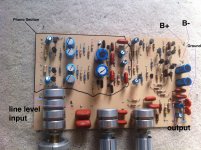
Well I had an extra PC-4 board laying around (Pervious owner had butchered some traces, so I don't care about it.
I drew and labeled the phono sections, line in eyelets, and the output eyelets.
Also labeled the B+ and B- as well as ground.
Just wanted to make sure I got it right.
How does it look?
I drew and labeled the phono sections, line in eyelets, and the output eyelets.
Also labeled the B+ and B- as well as ground.
Just wanted to make sure I got it right.
How does it look?
Attachments

Well I had an extra PC-4 board laying around (Pervious owner had butchered some traces, so I don't care about it.
I drew and labeled the phono sections, line in eyelets, and the output eyelets.
Also labeled the B+ and B- as well as ground.
Just wanted to make sure I got it right.
How does it look?
Looks good to me.
G²
- Status
- Not open for further replies.
- Home
- Amplifiers
- Solid State
- Breaking a Hafler DH-101 into Sections