Thanks a lot for doing the legwork on this. I just ordered two sheets through DoItBest to be delivered to a store near me. Fingers crossed.
Regards,
John
Regards,
John
I got the polyboard ...
Happy to report to all that I got the Polyboard delivered (for free) to a local "mom and pop" hardware store via "DoItBest.com". I had to wait a couple of weeks for the store's "normal" restocking delivery but it is very slick!! Thanks much to Tubelab.com for this great tip!! 😀
Happy to report to all that I got the Polyboard delivered (for free) to a local "mom and pop" hardware store via "DoItBest.com". I had to wait a couple of weeks for the store's "normal" restocking delivery but it is very slick!! Thanks much to Tubelab.com for this great tip!! 😀
Great news. I bet I'll have mine next Tuesday then.
Looks like DoItBest.com is the way to go and have it delivered to a local HW Store.
Saves on shipping too. 🙂 That almost cuts the cost in half!
Looks like DoItBest.com is the way to go and have it delivered to a local HW Store.
Saves on shipping too. 🙂 That almost cuts the cost in half!
Dang, I find it and everyone else gets theirs first.
Knowing my luck y'all will get it all and mine will go on back-order!
😡
Knowing my luck y'all will get it all and mine will go on back-order!
😡
I find several places selling it including a chain called "Do it Best" which has several stores in Colorado. It is not in stock but they have a "site to store" shipping service that is free.
😛😛 Na, Na, Na, Mr. Tubelab.com posted this on Jan 14th! 😛😛

Finders Fee
Hey Gimp and All --
Check out this great deal on eurostrips!!!!!!
http://cgi.ebay.com/Terminal-Strip-...emQQptZLH_DefaultDomain_0?hash=item255890aec4
Hey Gimp and All --
Check out this great deal on eurostrips!!!!!!
http://cgi.ebay.com/Terminal-Strip-...emQQptZLH_DefaultDomain_0?hash=item255890aec4
Poly Pegboard arrived yesterday but I didn't get a chance to get it till today. Nice looking stuff. A bit flimsy and might need some support ribs under the center.
I've been thinking about the guide pins. I wonder if Fluted wooden Dowels would work. They are available in 1/4" X 1-1/4" and 5/16" X 1-1/2". A box of a hundred is around $2.
Hot Glue? RTV? Epoxy?
Wood Fluted Multigroove Dowel Pins
I've been thinking about the guide pins. I wonder if Fluted wooden Dowels would work. They are available in 1/4" X 1-1/4" and 5/16" X 1-1/2". A box of a hundred is around $2.
Hot Glue? RTV? Epoxy?
Wood Fluted Multigroove Dowel Pins
Did anyone get the Eurostrips?
How do they look?
Through hole lead on the bottom?
I can't tell from the pix.
How do they look?
Through hole lead on the bottom?
I can't tell from the pix.
Guide pin idea
I was able to find some 3/8 in OD nylon rods on EBAY (5pcs. Nylon Rods 3/16" DIAMETER 12" long - eBay (item 270526469705 end time Mar-06-10 16:53:13 PST))
My thought is to cut them to 1 inch in length and "flatten" one end with heat to make the top of the pin. I would insert the flattened through the holes in the top of each "module". Then I would cut garden variety fish tank air hose into 1/2 inch lengths and push this hose on the bottom side of the pin to "lock" the pin in place without glue. The hose I have has a ID of 3/8 for a snug fit and an 0D of 5/8 which cannot go though the peg board holes. This also provides a 1/2 inch offset beneath the module in case I ever want to do any specialized wiring. This offset would also allow me to use top mount sockets in the modules without squishing the wires between the bottom of the module and the top of the breadboard.
A bit busy lately so I have not been able to actually hatch this scheme completely -- but it "should" work. Will report back. 🙂
Last edited:
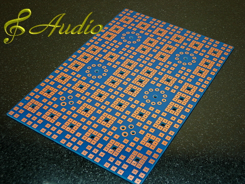
Here is another idea...
These boards are available on ebay. I have one of these boards. Good quality.
The last pic is from shine7.com. Nice solder posts.😎

These boards are available on ebay. I have one of these boards. Good quality.
The last pic is from shine7.com. Nice solder posts.😎
An externally hosted image should be here but it was not working when we last tested it.
Bump!
I'm finally getting around to making my breadboard and am wondering if I really need to make it 24" X 24". It will protrude off my workbench if I make it that large, but if it is really Necessary/useful I'll make it that big.
I'm thinking 20"X20" should handle two channels with 6L6 output tubes, phase splitters, drivers, input tubes, etc, so 20"X20" Might be enough. But, I don't want to shortchange myself.
Looking at the Tubelab setup it looks like it is 24"x24".
The Tubelab
I guess George is in the best position to answer my question about size and does it matter?
Have you found the 24" X 24" to be excessive, sufficient, insufficient? Have you ever used the full surface?
The 6AV5 setup looks like it takes up less than half the board.
Are 3" x 3" plug-ins sufficient for most tubes, etc with transformers taking up more space?
Thanks.
Vacuum Tube Experimenter's Prototype PCB
Classic Valve Design - Original and Legacy Design PCB's
Classic Valve Design - Original and Legacy Design PCB's
An externally hosted image should be here but it was not working when we last tested it.
a good friend an i cooked up a pair of these. they have a 20" x 30" work area. we made several improvements and built just one improved prototype. sadly i don't have any shots of it in my gallery. they use octal and 11pin relay DIN rail mount sockets. the we fab. 9pin sockets to fit in 11pin relay sockets.
http://i2.photobucket.com/albums/y11/pmitchel/agua-dulce-proto.jpg
http://i2.photobucket.com/albums/y11/pmitchel/agua-dulce-proto.jpg
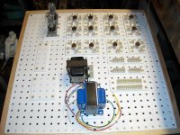
I've got the basic Tube Lab built along with an assortment of socket and other inserts.
I have a couple of observations for anyone else building one of these.
(1) Size:
24" X 24" (70cm x 70cm) is a nice size depending on your bench available space. Half a sheet leaves lots of material for inserts. Smaller would certainly compromise the available area. 30" X 24" would be nice if you want to breadboard two channels for full blown comparison.
(2) inserts.
Various form factors:
3"X3" (7.62cm x 7.62cm) good. supports 7 pin, 9 pin and octal sockets easily.
4"x4" (10.16cm x 10.16cm) not so good. too small for 30W transformers(Edcor 30W 5K MS in the picture), too big for tubes. Skip this size.
5"x5" would probably be a good size for large transformers. Unfortunately I did not anticipate this and did not make any this large.
1" x 6" or 1" x 8", ... Good for mounting terminal strips (Eurostrips) for connecting components. The Eurostrips I have might fit a 1" x 5" strip.
(3) Assembly :
Hot Glue Gun works great for attaching Eurostrips and pegs to peg board.
1/4" fluted pegs are great for alignment pegs.
The plastic pegboard cuts easily. A table saw or skill saw is nice, but a hand saw (cross cut for easy clearance) works fine. The plastic does not melt and jam a table or skill saw like Plexiglas will.
Once I start assembling an amp for testing I'll post more hints and kinks if I see anything really interesting.
Attachments
Hello,
I have used old school plywood that looks like a breadboard with an assortment of eurostrips screwed down as needed. For octal bases I use an 8-pin relay base with screw down connections Potter Brum Field 27E122 Octal http://apexjr.com/images/PotterSccket.jpg. I supose that these relay sockets will also work with the poly peg board.
thegimp I see that you also use the relay sockets.
DT
All just for just for fun!
Last edited:
a good friend an i cooked up a pair of these. they have a 20" x 30" work area. we made several improvements and built just one improved prototype. sadly i don't have any shots of it in my gallery. they use octal and 11pin relay DIN rail mount sockets. the we fab. 9pin sockets to fit in 11pin relay sockets.
And what's cooking here? I see a well-used Jim Dunlop guitar pick, and cannon sockets, is this for guitar amp, or recording, or maybe multipurpose?
My only concern about the relay sockets is the 300V rating.
I'm using Dayton 5X852E sockets which specifically state 300V AC. Some only say 300V.
I ran a hi-pot on alternating pins on one socket and quit when it passed 4KV dc for one minute with less than 0.01mA leakage.
I expect these sockets to work fine up to 600V figuring an additional 550V swing on a choke or transformer for a max peak voltage of 1150V.
I also tested an IDEC SR3P-05 11 pin socket at 4KV DC and it passed with less than 0.01mA leakage.
Other sockets may or may not be as robust.
- Status
- Not open for further replies.
- Home
- Design & Build
- Equipment & Tools
- Breadboarding/Prototyping - How to and Tips/Tricks