Hi,
This is my fist post in this forum. I'm new the tube and i want make a breadboard for learn. can you recommend me a system of protoboard?
Thanks for all information and answers
This is my fist post in this forum. I'm new the tube and i want make a breadboard for learn. can you recommend me a system of protoboard?
Thanks for all information and answers
Something like this?
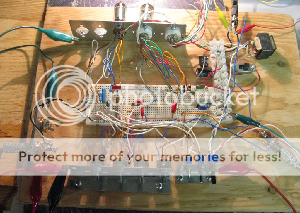 Notice that high voltage potential points are separated by 2 or 3 rows. I also use a metal plate under the the plywood that I ground, gets rid of most of the hum.
I have made several different breadboarding systems over the years. Two are shown in the link. They both require considerable bench space, which limits their use in my smapp lab.
The Tubelab
The Tubelab
I built the second version in the tubelab link, with the plastic perfboard and will attest to it taking up room.
But, it's nice.
But, it's nice.
Yeah, mine look a little like the Tubelab set-up ... with Fahnestock clips.
I made them little modules, but the more I've used it, the more I realize there are not too many amp topologies. You could almost lay out a SE or PP amp with Fahnestock clips for the various caps (coupling, etc.) and resistors (grid, etc.) that hang around.
I made them little modules, but the more I've used it, the more I realize there are not too many amp topologies. You could almost lay out a SE or PP amp with Fahnestock clips for the various caps (coupling, etc.) and resistors (grid, etc.) that hang around.
Over the last years I worked on a 'tweaker friendly amplifier'. Besides prototyping (allowing easy exchange of smaller and larger components) I was looking for a system that can also work quite well and safely after prototyping/tweaking is done (so one doesn't need a prototyped amp on a 1D breadboard to a final chassis). I like working with hybrids or sand assisted PS, so I included large L profiles that act as side panels as well as heatsinks, and more heatsinks can be added to the top op the amp if needed.
Meanwhile I had a lot of new ideas, but will have to wait until I am back from Maputo, Mozambique to test them out.
The thread http://www.diyaudio.com/forums/tubes-valves/202314-putting-together-tweaker-friendly-amplifier.html
Meanwhile I had a lot of new ideas, but will have to wait until I am back from Maputo, Mozambique to test them out.
The thread http://www.diyaudio.com/forums/tubes-valves/202314-putting-together-tweaker-friendly-amplifier.html
Nice lab Avincenty, can you share more detail and pics?
Cheers
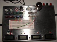
I dont have details of the build. The 4 meters are: 1 250ma, 1 200v and 2 500v. I put these since a few of my HV supplies do not have built in metering. 1/2 of the 9 pin sockets have share the same heater voltage. The 8 pins and the other 1/2 of the 9 pins share another.
Initially i labled the 9 pins for the 12ax7 pinout. I later numbered the jacks so i could use any other pinout.
I added another breadboard for flexibility, i also use it to test solid state stuff.
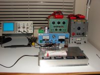
I also purchased from craigslist a HK A300 and thoroughly went through it with voltmeters and oscilloscope. Learned a lot doing it.
Very important was obtaining the power supplies. Luckily i was living in LA at the time and found vintage gear for 20 a pop.
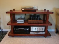
From there i tested A PP configuration and played with tone controls. My first build soon after that is the larger tube amp in the middle shelf. The HK A300 is below.
Attachments
hi,
I'm very happy for the information, thanks. I think now which is the best option for me but i find very interesant the option of tubelab with the individual modules.
Thanks
I'm very happy for the information, thanks. I think now which is the best option for me but i find very interesant the option of tubelab with the individual modules.
Thanks
I've used a "peg board" made from a piece of plywood and some brass nails for prototyping. That's a bit of a pain to work with, though. My favorite is a scrap piece of FR-4 PCB material with holes drilled in it for the tubes. I use some terminal strips for connecting components. That works well enough to allow me to debug the circuit before committing to a PCB layout.
You can see examples of both methods here:
http://www.diyaudio.com/forums/tubes-valves/157453-6lu8-spud-request-comments.html#post2026883
~Tom
You can see examples of both methods here:
http://www.diyaudio.com/forums/tubes-valves/157453-6lu8-spud-request-comments.html#post2026883
~Tom
I dont have details of the build. The 4 meters are: 1 250ma, 1 200v and 2 500v. I put these since a few of my HV supplies do not have built in metering. 1/2 of the 9 pin sockets have share the same heater voltage. The 8 pins and the other 1/2 of the 9 pins share another.
Initially i labled the 9 pins for the 12ax7 pinout. I later numbered the jacks so i could use any other pinout.
I added another breadboard for flexibility, i also use it to test solid state stuff.
I think this is a great idea, compact, with space to add more 🙂
Any chance you could post a top and internal view?
Cheers
I've used prototyping pcb boards sold on Ebay by various Chinese sellers. You can find them by searching "prototyping pcb board tube".
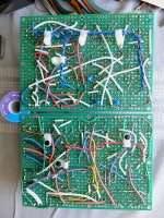
They have footprints for several 7, 8 or 9 pin tube sockets, size 150x200mm barely enough to assemble all the power push-pull amplifier stuff, thickness 1.6mm makes them too flexible and fragile to cracking.
Images of prototyping boards with KT88 Williamson ans floating paraphase /push-pull attached.
Extra terminals soldered on board used to switch between penthode, UL, triode and CFB modes, turn GNFB on and off, and attenuating RC networks. Very handy to tweak and debug amplifier.
Attachments

- Status
- Not open for further replies.
- Home
- Amplifiers
- Tubes / Valves
- breadboard for tubes