I recently took it upon myself to build a nice preamp from some schematics I found online. Elliot Sound Design provides schematics for both a preamp and a suitable PSU (P06 and P05) that I ended up putting together (first version of each for simplicity).
I thought I'd have a little fun and try building it just from the free circuit diagram of the basic first versions of the projects provided on the site. I built the psu and etched a nice little board once I confirmed it was working (+/-15v).
However, I am unable to get the preamp circuit to amplify at all on my breadboard.
I have a decent amount of experience on breadboards/following diagrams (3rd year electronics student) so I'm confident the circuit is correct (not to mention the 10 times I've reassembled the darn thing) so I've narrowed it down to a few things that could still be wrong that I'd like to confirm here.
Troubleshooting:
I get phono volume coming out of my speakers (very very quiet) with a lot of interference (it's on a breadboard haha) but there is no amplification at all.
I tried wiring a piezo speaker to the input to try a different source but that yielded no amplification either.
My multimeter shows no change in DC voltage between the input and output in both cases (input measured separately).
Theories:
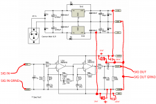
1. Wired together incorrectly - I have the signal out of the turntable going through my preamp circuit then out to my regular amplifier with the ground of the psu, preamp, and sig i/o all wired together in one big heap. I have attached a picture of how I have the projects wired. I have no doubt that mine matches what I have drawn it is that I'm unsure what I have drawn is the correct way to wire it all together. So if someone could confirm what I have drawn is indeed correct that would be very helpful.
2. Component incorrect/missing - When you buy the PCB from ESD they advise waiting for it to arrive before buying components as they provide very detailed specific instructions as of what to buy. There is a chance I purchased a component that is the correct values just the wrong type. I'm also thinking they left something key out of the diagram. With my basic understanding of opamps I can see how it basically works but can't tell if anything crucial is missing. If someone with a better understanding could confirm that the supplied preamp circuit on its own should work that'd be great.
3. Wrong 1uF capacitor - I had difficulty finding a non polarised 1uf capacitor so I ended up using one designed for crossovers (1uf Polypropylene). I tried a couple of different capacitors in its place (bipolar/shorting) since I was a little unsure but still no amplification.
Ideally I was thinking if I could strip the circuit back to a basic point where I could confirm it is working then add stuff to it until it breaks that would work really well.
I thought I'd have a little fun and try building it just from the free circuit diagram of the basic first versions of the projects provided on the site. I built the psu and etched a nice little board once I confirmed it was working (+/-15v).
However, I am unable to get the preamp circuit to amplify at all on my breadboard.
I have a decent amount of experience on breadboards/following diagrams (3rd year electronics student) so I'm confident the circuit is correct (not to mention the 10 times I've reassembled the darn thing) so I've narrowed it down to a few things that could still be wrong that I'd like to confirm here.
Troubleshooting:
I get phono volume coming out of my speakers (very very quiet) with a lot of interference (it's on a breadboard haha) but there is no amplification at all.
I tried wiring a piezo speaker to the input to try a different source but that yielded no amplification either.
My multimeter shows no change in DC voltage between the input and output in both cases (input measured separately).
Theories:
1. Wired together incorrectly - I have the signal out of the turntable going through my preamp circuit then out to my regular amplifier with the ground of the psu, preamp, and sig i/o all wired together in one big heap. I have attached a picture of how I have the projects wired. I have no doubt that mine matches what I have drawn it is that I'm unsure what I have drawn is the correct way to wire it all together. So if someone could confirm what I have drawn is indeed correct that would be very helpful.
2. Component incorrect/missing - When you buy the PCB from ESD they advise waiting for it to arrive before buying components as they provide very detailed specific instructions as of what to buy. There is a chance I purchased a component that is the correct values just the wrong type. I'm also thinking they left something key out of the diagram. With my basic understanding of opamps I can see how it basically works but can't tell if anything crucial is missing. If someone with a better understanding could confirm that the supplied preamp circuit on its own should work that'd be great.
3. Wrong 1uF capacitor - I had difficulty finding a non polarised 1uf capacitor so I ended up using one designed for crossovers (1uf Polypropylene). I tried a couple of different capacitors in its place (bipolar/shorting) since I was a little unsure but still no amplification.
Ideally I was thinking if I could strip the circuit back to a basic point where I could confirm it is working then add stuff to it until it breaks that would work really well.
Attachments
Use signal tracing to find the problem.
Connect a signal generator to the input...look at the output of the first opamp and see if you see the expected result.
If so, go to the second opamp and check again.
Given all the gain in the circuit, it's quite likely that there will be tremendous amounts of hum if the construction method isn't sound.
Akitika Preamp and Power Amp Kits
www.updatemydynaco.com
I'm putting my bets on something simple like the signal not making it into the first opamp, or from the first to the second stage. With plainly audible interference, the circuit seems to be powered and doing something at least. That may also be an indication of it oscillating wildly though. Breadboard is breadboard after all and has a few traps to offer. It certainly can't hurt to check all resistor values either.
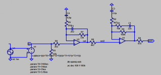
BTW, that circuit is not very well optimized. Its distortion performance and noise floor should actually improve when swapping the two stages around, at the cost of a single extra resistor for the output (big deal). Right now the noisier stage is at the input and the broadband amplifier is subjected to high levels. I've tweaked resistor values a bit and moved the 75 µs pole into the (now) first stage, the result being:

(Yes, those are ideal opamps, and there's an inverse RIAA at the input.)
BTW, that circuit is not very well optimized. Its distortion performance and noise floor should actually improve when swapping the two stages around, at the cost of a single extra resistor for the output (big deal). Right now the noisier stage is at the input and the broadband amplifier is subjected to high levels. I've tweaked resistor values a bit and moved the 75 µs pole into the (now) first stage, the result being:
(Yes, those are ideal opamps, and there's an inverse RIAA at the input.)
Attachments
Try some basic DC voltage tests with a meter. Use the input ground as a reference point and confirm that both opamps have a correct plus and minus supply voltage on pins 8 and 4 respectively. Also check that each opamp output pin is within a few hundred millivolts of zero. The type of 1uf cap won't make any difference, you could use a correctly polarised electrolytic.
BTW, that circuit is not very well optimized. Its distortion performance and noise floor should actually improve when swapping the two stages around, at the cost of a single extra resistor for the output (big deal). Right now the noisier stage is at the input and the broadband amplifier is subjected to high levels. I've tweaked resistor values a bit and moved the 75 µs pole into the (now) first stage, the result being:
(Yes, those are ideal opamps, and there's an inverse RIAA at the input.)
I'm interested in using this circuit.
So you have taken out what I assume to be the RIAA equalisation at the end of the original circuit (C4, C5, R9) and suggested I put it at the beginning? is that what V1 and E1 represent?
I'm a little unclear what E1 and V1 are. do I just put any old passive riaa inverse circuit in there?
I'll grab the new value capacitors/resistors and try the new circuit out hopefully sometime this week.
No, what I did was (in terms of the ESP schematic) :
* Move U2A including R6/7/8L and C3L/C4L in between R2L and U1A input.
* Tweak C2L/C3L for subsonic suppression (note: use bipolar types or two polars back-to-back)
* add R9 for output isolation (that's the single extra resistor I mentioned - note: chosen depending on opamp type, this value would be fine even with a TL072, one could go as low as 47R with a 5532 or OPA213x, and 100-220R would generally be fine)
* Downsize R values around U2A (for reduced noise) while adapting C3L, assuming a somewhat beefy opamp (original values would still be fine for TL072, but NE5532 should be fine with these)
* remove C4L and add new cap in U2A feedback path to replace it (C5 in mine, note time constant is given by C5*R7)
* Adjust R6 (R8L) for better impedance symmetry around U1L (anything from 3k3 to 4k7 should be fine)
V1 is a plain ol' voltage source, and E1 is a voltage-dependent voltage source that applies an inverse RIAA by means of a Laplace transform. These are just for simulation and checking (ideal) RIAA accuracy.
Note that right now, the 2k2 input series resistor is limiting noise at mid-low frequencies. More elaborate (L-C) input filtering may be used if it is to be reduced.
And yes, as mentioned earlier, grounding and layout better be sound. A grounded metal case is also recommended (ohmic connection at one set of inputs or outputs, a few 10 nF elsewhere), and don't forget a ground screw (connected to circuit ground via maybe 1k||100nF).
Last edited:
Try some basic DC voltage tests with a meter. Use the input ground as a reference point and confirm that both opamps have a correct plus and minus supply voltage on pins 8 and 4 respectively. Also check that each opamp output pin is within a few hundred millivolts of zero. The type of 1uf cap won't make any difference, you could use a correctly polarised electrolytic.
okok
I powered up my circuit and it was playing very very quietly on my speakers like normal.
I unplugged the power for the opamps and for 4 seconds it got INCREASINGLY louder. To about line level. Then no sound at all. (Capacitors discharged?)
EDIT: sorry I meant unplugged the power source for the opamp psu (power brick) and left my custom psu connected to the preamp
When it's powered on and playing very very quietly the voltage between the input ground and the +/- power power pins on the opamp are BOTH +1v.
EDIT: I just measured again under the same circumstances and it was actually +15v and -0.2 which makes sense since they should be the same as the psu outputs mentioned just after
The outputs on my powersupply board measure +15 and -0.2v from the psu ground.
When I disconnect the powersupply from the preamp circuit they measure +15 and -16.2.
Something definitely seems wrong with my powersupply circuit. I'll check that over tonight and report back.
Last edited:
Yes, definitely a problem with the power supply if you only have -0.2 volts.
Have you including the diodes shown in your diagram, D3,4 5 and 6 as these prevent lockup of the regulators under certain conditions ?
Check the voltages methodically while its in the faulty state, in particular that you have at least +18 and -18 volts going into the regulators.
Have you including the diodes shown in your diagram, D3,4 5 and 6 as these prevent lockup of the regulators under certain conditions ?
Check the voltages methodically while its in the faulty state, in particular that you have at least +18 and -18 volts going into the regulators.
I made an edit to my last post as it was a little unclear please read again just in case it was misunderstood.
I'll make those checks right now Mooly thanks.
I'll make those checks right now Mooly thanks.
Yes, definitely a problem with the power supply if you only have -0.2 volts.
Have you including the diodes shown in your diagram, D3,4 5 and 6 as these prevent lockup of the regulators under certain conditions ?
Check the voltages methodically while its in the faulty state, in particular that you have at least +18 and -18 volts going into the regulators.
I have meticulously gone over my psu board and can find no differences between it and the circuit diagram.
I remade the the psu in a simulation program to see if I was reading the diagram incorrectly.
it performed strangely connected to the preamp in sim. When powering the preamp it very slowly and logarithmically gets to -15.5v after about a minute where the other rail gets to 15v instantly.
This doesnt occur when the psu isnt under load in simulation either. the negative rail gets to -15v instantly.
in my real world tests my the powersupply stays at 0.02v when it's connected to the preamp (under any load) and 16v not under load. To make sure the preamp circuit wasnt affecting this uniquely I connected the ground of the psu to a motor and tried the +/-15v rails on it. The 15v one made it spin and the -15v gave it a tiny jitter but practically noting. So the negative rail definitely isnt performing under load.
I measured the negative rail when I "disconnect power to the psu and it gradually increases volume to line level over 5 seconds then cuts out" but it stays at -0.02v surpsingly over this.
overall there is at least something definitely wrong with the negative rail of my psu but I can't find any differences between the diagram and my circuit. The simulation also seems to perform strangely in similar ways. Could something be wrong with the diagram? I understand how the voltage doubler works and have run through it on my circuit board to make sure the logic works.
The specific regulators I have are L7915CV and 7815CT.
The voltage going into them at all times is 24v.
The power brick I'm using to power the psu is outputs 16v 50hz 1.5A AC.
Voltage into the regs should be PLUS 24 and MINUS 24 for the 7815 and 7915 respectively.
The diagram looks fine. With 16 vac applied it has to generate the -/+24 volts.
Don't loose sight of performing basics tests.
Concentrate on the negative rail and confirm that you have -24 volts on the input pin while at the same time seeing only 0.2 or whatever on the output. Double check that result by measuring the voltage differential across the reg. You would have to see around -24 volts in that case... but check it.
Could the negative rectifier diode be faulty/high resistance or could there be a bad joint in that negative feed to the reg.
When measuring, do it on the pins of the reg itself, not on the board on print.
Does the reg or diode, or any cap get hot ?
My mistake, the measured value on the input of the neg reg was -24v.
I took the negative channel off my psu board and moved it onto a breadboard replacing all 3 diodes with new ones. I wired it up and it performs with the same issues.
The negative regulator does get pretty warm comparatively. I ordered a new 7915 in case I accidentally busted it during breadboarding. All the other components don't get noticeably warm.
I checked the voltage on the regulator:
-24.8v between vin and gnd (negative probe on gnd)
-24.5v between vin and vout (negative probe on vout)
At this point I'm placing my bet on a busted 7915. At this stage I'll probably wait till the new one gets shipped then report back.
(btw it was silly of me to question the diagram. naive uni student in me coming out haha)
Last edited:
I just did a more complete measurement of the voltages around the 7915 regulator.
NO LOAD
-8.2v vin vout (pos probe vin)
-24.4v vin ground (pos probe vin)
-16v vout ground (pos probe vout)
LOAD (conected to preamp)
-24.1v vin vout (pos probe vin)
-24.3v vim ground (pos probe vin)
-0.1v vout ground (pos probe vout)
NO LOAD
-8.2v vin vout (pos probe vin)
-24.4v vin ground (pos probe vin)
-16v vout ground (pos probe vout)
LOAD (conected to preamp)
-24.1v vin vout (pos probe vin)
-24.3v vim ground (pos probe vin)
-0.1v vout ground (pos probe vout)
There are a couple more tests you can do here.
First is to measure the current drawn from the output of the reg. The safest way to do this is simply place a series 1 ohm (or even 10 ohm) resistor in the feed and then calculate the volt drop from the result.
You can also test the power supply itself by disconnecting it from the preamp and connecting a dummy load across the rail. 150 ohm would draw 0.1 amp. If you were quick with the measurement then a half watt carbon/metal resistor would survive long enough to get a reading.
These regs have current limiting and 'foldback' limiting and I'm just wondering if something on the preamp is causing this.
And yes, its possible it is a faulty reg at the end of the day.
there might very well be issues with my preamp circuit too but the motor test confirmed something is at least wrong with the the negative rail independent of the preamp. Since I've redone all the connections to a breadboard and replaced the diodes I think it's something wrong with the regulator (still possibly the capacitors or how I'm wiring it though)
I'll hold off further testing since I have high hopes for this new regulator. I ordered the regulators locally so they should be here within a week
Thanks for all your wonderful help, this has been a lot of fun 🙂
I'll hold off further testing since I have high hopes for this new regulator. I ordered the regulators locally so they should be here within a week
Thanks for all your wonderful help, this has been a lot of fun 🙂
In the meantime, you could also try out the single supply version (P06 page Fig. 3). Changes are pretty minor really, you mainly need to combine -15V and PGND, observe C2L/C3L polarity, reroute R1L and add a handful of components with fairly non-critical values so that the input is brought up to half supply internally. (Note: Cx1 can be any ordinary small electrolytic as well, like a 10µ/50V or something, (-) facing the input.)
As shown, performance should also still be OK on an unregulated single supply actually, a bit of hum maybe (connecting a cartridge should mostly take care of that). You could try your +24V assuming your 10µ caps can take it... and your C5L of course, which like the input cap must withstand half supply.
As shown, performance should also still be OK on an unregulated single supply actually, a bit of hum maybe (connecting a cartridge should mostly take care of that). You could try your +24V assuming your 10µ caps can take it... and your C5L of course, which like the input cap must withstand half supply.
Last edited:
New regulator worked! Onto building!
I'll probably have a few more issues bringing this off the breadboard and finalising so stay tuned for that...
I'll probably have a few more issues bringing this off the breadboard and finalising so stay tuned for that...

quick update:
I have the final boards finished and wired together and everything it's sounding fine 😀
The case is coming together nicely I just need to replace my RCA connectors with insulated ones.
But I just noticed something with the power supply schematic. Two of the rectifier diodes are on the output sides of the regulator? (D4 and D6) so half of the full wave bridge is on the output? shouldnt those two diodes be on the input side so I'm fully utilizing the regulators? Or does this have something to do with the voltage doubler on the input and will break that...
oh and another question. My turntable doesnt have a grounding cable and my AC wall adaptor for my preamp doesnt have a connection to earth so I can't ground the case properly. I'm thinking of maybe replacing the the power cable to my TT with a 3 prong one and giving it a ground output and wiring it to my preamp so it gets proper shielding and I can ground the signal to it via res||cap like sgrossklass said.
Does this sound like a good idea? Would I connect both the tone arm and TT chassis to this ground too?
- Status
- Not open for further replies.
- Home
- Source & Line
- Analog Line Level
- breadboard ESD P06 Preamp not amplifying