opt
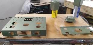
so what with parts missing - im feeling rather happy about taking the opt's off the chassis and out of the covers for painting ------ as i find the common has had a mounting screw cut half way through it !! ffs -- i would not have known albeit any other colour could have been worse !!!
so what with parts missing - im feeling rather happy about taking the opt's off the chassis and out of the covers for painting ------ as i find the common has had a mounting screw cut half way through it !! ffs -- i would not have known albeit any other colour could have been worse !!!
Attachments
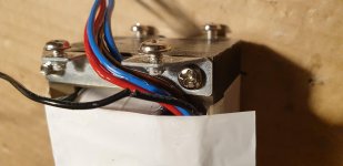
It looks like the black wire has been cut on your transformer, Post # 23.
And, you have not said anything about your Power Transformer.
Did you get one?
The more I see and hear, this reminds me of the "Open Box" Special.
Not so special after all.
And, you have not said anything about your Power Transformer.
Did you get one?
The more I see and hear, this reminds me of the "Open Box" Special.
Not so special after all.
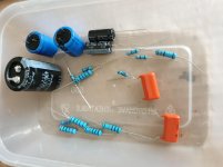
I know its cut , thats what my post was about , I wasn't planning on getting power transformer as its OK, I had thought about getting better opt's as previously mentioned , looks like my kit is a sack of shite really so could end up a very expensive chassis !!!! , from douk store if interested , I will press on and probably replace all the wires on the opt's , BTW thinner wires as I thought are secondary, you thought maybe the thicker? I'm sure all will be ok , at least all my components are good q
As to the cut wire, finish the cut.
Then carefully strip 1/4 inch at the ends, tin them, and solder to join them, then cover with Shrink Tubing. I would not try and fish out the beginning of the wire all the way to the enameled wire end of the winding.
Nobody will see, but it will be safe, if you do the following:
Be sure to use a rubber grommet for the wires to go through the chassis, or do a very good job of de-burring and filing any and all sharp metal of the chassis hole.
When you get the amp up and running, you will have something to be really proud of.
So much work deserves a reward.

Nice looking layout 🙂
Just one thing, move the 39Ω to pin 8 of the rectifier valve otherwise you are drawing all the current through the heater element.
Just one thing, move the 39Ω to pin 8 of the rectifier valve otherwise you are drawing all the current through the heater element.
A9
Dave realised that and now corrected --- would you know ?? should i leave that cap off of the power switch ? i have a lorlin type to use and i did read somewhere here its safer not to have that cap fitted -- im still learning but taking much time and doing much research -- i will also fit balanced resistors on the 6.3v taps -- no harm doing both i guess
Dave realised that and now corrected --- would you know ?? should i leave that cap off of the power switch ? i have a lorlin type to use and i did read somewhere here its safer not to have that cap fitted -- im still learning but taking much time and doing much research -- i will also fit balanced resistors on the 6.3v taps -- no harm doing both i guess
Nice looking layout 🙂
Just one thing, move the 39Ω to pin 8 of the rectifier valve otherwise you are drawing all the current through the heater element.
almost ready to power up - have variac for that purpose - im still unsure about the mains switch and that cap -- is it good enough ?
The cap across the switch is just an arc suppressor to prolong the life of the switch contacts, i used the same switch in my amp and didn't bother with it.
Phil
Phil
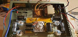
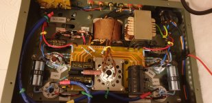
its alive !!
so here we are , absolutely fantastic first time round - no hum - buzz - or hot transformers - spot on voltages locked at 225v on variac
i took about 3 hrs to slowly bring everything to life -- stock tubes at the moment apart from svt 5u4g rectifier
so here we are , absolutely fantastic first time round - no hum - buzz - or hot transformers - spot on voltages locked at 225v on variac
i took about 3 hrs to slowly bring everything to life -- stock tubes at the moment apart from svt 5u4g rectifier
Attachments
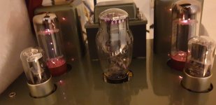
still on test
so how if possible can we get a bit more out of these amps ?? ive got some 6sl7gt's on their way and maybe go for kt77 - so that should be adequate for the tube department - but what can be done internally ?? - trouble is at the moment i have nothing more than a multi meter and the internet - to be honest i simply couldnt believe my efforts turned out i reckon spot on - will re test voltages in a few hours once its had some time - played about 2 faultless hrs of blues so far
so how if possible can we get a bit more out of these amps ?? ive got some 6sl7gt's on their way and maybe go for kt77 - so that should be adequate for the tube department - but what can be done internally ?? - trouble is at the moment i have nothing more than a multi meter and the internet - to be honest i simply couldnt believe my efforts turned out i reckon spot on - will re test voltages in a few hours once its had some time - played about 2 faultless hrs of blues so far
Attachments
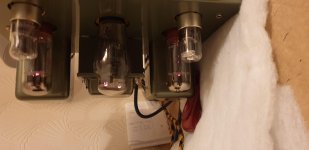
another pic
another idea i had - if poss ?? - could this be made switchable from intergrated to simply a power amp - but for now some more output would be good -- or maybe im expecting too much from set el34 ? - its loud at 12 o clock with more to go - i did wind it right up but gets a bit distorted at max volume - sound got a bit wobbly ! take it back a touch from max its ok - speakers are Klipsch r51 92db jobs
another idea i had - if poss ?? - could this be made switchable from intergrated to simply a power amp - but for now some more output would be good -- or maybe im expecting too much from set el34 ? - its loud at 12 o clock with more to go - i did wind it right up but gets a bit distorted at max volume - sound got a bit wobbly ! take it back a touch from max its ok - speakers are Klipsch r51 92db jobs
Attachments
Generally, more power requires more B+ voltage, and more output stage current.
And then, you can not use too much of those, or the output tubes will be beyond their plate and screen dissipation limits.
Some more powerful output tubes require more filament current, and that requires a different power transformer.
But higher B+ voltge and current requires a different power transformer, and also different output transformers that can take more current.
Now, Exactly what is the schematic of YOUR A9?
Perhaps a different output transformer can make some improvements.
Power (depending on the mode, Pentode, Ultra Liner, Triode.
Low frequency response
Low frequency distortion
Or . . .
Less power but more finesse
So much depends on Your parts, and Your schematic.
There are limits to all of this, in some cases you just need to build a totally different amplifier.
- Home
- Amplifiers
- Tubes / Valves
- Boyuu A9 - just purchased the kit !!