Hello everyone - im late to the Boyuu party so it would appear ?
ive built a few amp kits so not entirely clueless but im somewhat holding back on the start of building , so my main pc board would appear different to the one shown on the sale - i appear to be missing the resistor for R301 --- 39/6w - and the other 2 large wire wounds - no substitutes included !!
i have seen many posts here regarding this amp and quite honestly i feel lost now , so many differant views and mods !!
does anyone have a pretty much out the box amp built ??
i also see a few have upped the caps somewhat - 330u on C302 ??
cathode bypass caps
bleed resistors etc etc etc
change the orange drops for example
it would be so helpful if i could simply find an A to Z start to finish page for this thing
most of the insides of these builds all look very differant on these posts , im not a fully fledged electronics engineer so i need to read most stuff in simple terms haha
so can anyone point me in the right direction ?
the basic proven upgrades would also help please , esp for the safety etc
Chris
Basic rule for doing modifications . . .
Get it to work un-modified first.
If it does not work in the beginning, a modification will probably not fix the problem that is causing it not to work.
Just Sayin'
Did they give you a schematic?
Did they give you a wiring diagram?
What instructions did they give you?
Get it to work un-modified first.
If it does not work in the beginning, a modification will probably not fix the problem that is causing it not to work.
Just Sayin'
Did they give you a schematic?
Did they give you a wiring diagram?
What instructions did they give you?
A9
No i got nothing but the kit with a bag of parts - resistors mentioned are missing , my board is differant to most others i see around the R301 area
why i ask has anyone built one of these in stock form with this same board ? looks like i have to go through all these pages and do some searching -- ive seen a guy on utube Kris Rocka i think --- he has the same board etc so i have messaged him too
brgds
Just an idea of what to try . . .
Post the link of where you purchased the amp;
And Post a link of the exact model you purchased.
Then perhaps someone will recognize it as exactly the same as what they have,
and how they built it.
Post the link of where you purchased the amp;
And Post a link of the exact model you purchased.
Then perhaps someone will recognize it as exactly the same as what they have,
and how they built it.
neat looking amp - - do the output transformer covers "slip off" to reveal the transformer's actual size / core stack?
Do I need to upgrade my computer?
I do not see any pictures on this thread, from Posts # 1 to # 6.
I do not see any pictures on this thread, from Posts # 1 to # 6.
"This" is the source I found. I think its common to find tall transformer covers to give an even aesthetic, hence my question to OP
REISONG Boyuu A9 EL34 Single-ended Pure Class A tube amplifier DIY Kit : China-hifi-Audio online store, Yaqin,Meixing Mingda,XiangSheng,Line Magnetic Tube Amplifier, power amp, preamp,hi-fi CD Player high end audio for sale [MUIA9831299] - $199.89 USD
The version with plain output transformers is beautiful
Last edited:
Do I need to upgrade my computer?
I do not see any pictures on this thread, from Posts # 1 to # 6.
Because i havnt had time today !! 🙁
200 bucks, missing parts, no instructions??
I'd send it back except the shipping must be brutal.
The listing does say "If you are an entry-level DIYer, please don't buy the KIT." Which maybe would not apply after "a few kits", except for the parts and instructions/docs problems.
I'd send it back except the shipping must be brutal.
...ive built a few amp kits so not entirely clueless but im somewhat holding back....
The listing does say "If you are an entry-level DIYer, please don't buy the KIT." Which maybe would not apply after "a few kits", except for the parts and instructions/docs problems.
Ok good people i have spent a few hours and reached page 100 of these posts , i can now work out what is required etc - i have decided to order up a few parts before i start , all the resistors for example ! mostly because i have some missing !! but i will get slightly better quality metal films i guess , tube sockets i will also get along with slightly better caps - all of them !
i think some better screened cable is a must as whats supplied is poor as hell !
once i have everything to hand i will come back with hopefully happy news and will upload some pics
thanks muchness to you all
Chris 😱
i think some better screened cable is a must as whats supplied is poor as hell !
once i have everything to hand i will come back with hopefully happy news and will upload some pics
thanks muchness to you all
Chris 😱
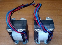
I attach a picture of the output transformers without the cover. They are tiny but good enough for a bookshelf speaker. The kit purchased by Chris may have slightly different transformers, because this kind of low-end kits seems to be assembled with the parts currently at hand by the manufacturer, as Chris found out. I've helped a few people building cheap china-sourced kits and I've see many variations. There are funny part substitutions sometimes, such as an extra volume pot instead of a filter capacitor: they are equivalent in a sense that they cost roughly the same to the manufacturer. Those kits are not meant to be built by inexperienced people, but I'sure that Chris will sort out the issues and will build a nice amplifier. I suggest to buy one of those low-cost component testers with LC function to measure the ESR and the leakage of the supplied electrolytic capacitore before installing them. The wiring arrangement of the power transformer must be checked carefully because wire colors aren't matching with the supplied schematic sometimes, and a mistake will mean a dead transformer. Discard and replace the power switch if it does not bear a CE or UL safety mark (they may be unsafe).
Attachments
Hi - so im nearly ready to make a start , i decided to simply replace all the resistors with better ones rather than mix mine with the kits missing items , also have decided that i dont like black - so as i own a car restoration business its now Aston Martin California sage green metallic ! i am going to attempt downloading some pics
i have the same opt's - i guess they simply think that no markings or labels is fine and everyone will know/think the thinner leads are secondary's ?? - i am thinking of getting better ones , the only opt's i can find new are from primary windings - 3.5k = 10w , they have higher output ones too but they are too big to fit on top of this chassis
i have the same opt's - i guess they simply think that no markings or labels is fine and everyone will know/think the thinner leads are secondary's ?? - i am thinking of getting better ones , the only opt's i can find new are from primary windings - 3.5k = 10w , they have higher output ones too but they are too big to fit on top of this chassis
I believe your chassis holes are already there to mount the output transformers.
Build your amp with the supplied output transformers first.
Get it working, then listen.
Then you can think about some new output transformers.
There are several different schematics for these kit amplifiers.
Some are Triode wired; Ultra Linear; and Pentode/Beam Power outputs; with or without negative feedback.
Knowing the circuit will help to identify a better output transformer that fits.
Of course, the selection will depend on whether they are local to you, and shipping and duty costs.
Thinner Wire is primary, thicker Wire is secondary (hopefully). Primary may, or may not, have Thicker Insulation, for a higher voltage rating.
Last edited:
how on earth are they expecting some guys to know that ?? because the opt's look nothing like their drawings !!
as i said before i dont know a massive amount but had hoped it was enough - is there an easy way of testing them with a MM with no load going through them ? im not thick by any means but why even produce transformers for kits with no markings whatsoever - Regarding all my missing parts ive had a week of excuses telling me not to worry it ! hence why ive just got all fresh ones - same can be said for caps they dont look proper brands to me - again using my own but going to go with 33uf and 330uf - as suggested somewhere else here - happy to start now but the transformers im gonna have to triple check !! - not seen my pics up yet albeit seemed to be taking ages to load
Chris
Typically, an analog VOM can test Ohms better on an output transformer, than an Auto Ranging DMM.
Set the DMM to medium ohms range (like 999 Ohms).
Use a known resistor to check the range you are in.
Check for multiple wires that connect to each other, but not to other wires.
Check for the other group of multiple wires that connect to each other, but not to the first group.
One group is the Primary.
One group is the Secondary.
The low resistance ones are the secondary.
The primary will have at least 2 wires (simplest single ended primary, B+ and Plate).
The primary may have 3 wires (B+, Plate, and Ultra Linear tap).
The highest resistance across 2 of those wires is B+ and Plate.
The lowest resistance across 2 of those wires is B+ and Ultra Linear tap.
The medium resistance across 2 of those wires is Ultra Linear tap, and Plate.
Now, switch the ohmmeter range to the lowest range.
The secondary is similar. The highest resistance is from Common to the largest impedance output tap.
There is probably at least one more tap, maybe two taps more.
These are all DC resistance of 1 or 2 Ohms or less.
You have to really be sure the ohmmeter leads are very well connected to the secondary leads.
Common, 4, 8, 16.
Pretty hard to determine more (like which is 4 and which is 8) until the amp is built.
Common, 4, 8. The 4 Ohm tap will be the lowest resistance to the C tap, and the lowest resistance to the 8 tap.
The C to 8 will be the largest resistance.
If you reverse B+ and Plate, no problem.
If you reverse Common and 8 Ohm no problem.
(as long as your circuit does not use negative feedback).
It will work for one channel.
It will work for the other channel.
When you go to Stereo, they need to be matched, so the phases match.
Unmatched phases causes 2 things:
The bass frequencies of the L and R speakers cancel.
The sound seems to be Outside (beyond) the left and right of the speakers.
Last edited:
- Home
- Amplifiers
- Tubes / Valves
- Boyuu A9 - just purchased the kit !!