While the cab can be considered technically too large, it allows more tuning flexibility, hence the recommendation. FWIW, I used hardboard/Masonite and/or thin furniture grade plywood not only to make drivers flush, but as the base-plate of a grill, normally cutting all holes out with either a hole saw or jigsaw. I didn't get a router until the bulk of my speaker building days were behind me.
GM
GM
GM said:While the cab can be considered technically too large, it allows more tuning flexibility, hence the recommendation. FWIW, I used hardboard/Masonite and/or thin furniture grade plywood not only to make drivers flush, but as the base-plate of a grill, normally cutting all holes out with either a hole saw or jigsaw. I didn't get a router until the bulk of my speaker building days were behind me.
GM
Yes, I've used a piece of the handy panel size piece to make a grille frame already.
The router is still in the case without much action. I've made an alternate base plate for a tramel and for doing 'leleveling' cuts
that were only so-s- originally. I have a leaf in a table to mount it that way.
No jig saw here but I've got my eye on sales at Sears. Also FWIW I just saw a tool tip for the jig saw: Put a thick sole plate on it to increase blade life. Since the blade only travels a bit, making the
sole plate gives 2x the blade wear.
The last word
Some progress today and my first practical router experience.
I am still doing test cuts.
On the doc. sheet that comes with the 167e there seems to be 2 different figures for the speaker cutout: 6 inches or 146 cm. Then in the diagram it shows the figure upside down question mark 143.6.
What is the last word on this?
I am setting up a one time use tramel and once I commit to the cut,
that will be it.
I have made a front baffle of particle board laminated with hardboard
which will hopefully give a good surface to cut the necessary rabbet.
Re: The last word
If you use a plywood or particle board backer under your workpiece and a pin (1/4 dowel or steel pin) to act as the centre for your trammel, drill the hole well into the backer board, so you can replace the pin securely in the backer if necessary. Then improvise a method for replacing your baffle in exactly the same position later- either blocks clamped to index the baffle edges, or even nails through the baffle and into the backer (if you are going to paint or veneer later).
You should be able to make repeat cuts if necessary to 'fine tune' the hole size- no need for a 'one time' cut.
Guitar builders use a similar technique when cutting soundholes and routing for the rosette.
BTW, I just checked my 167e enclosures- the cutout is 144mm or 5.7" and the speakers fit fine.
Cheers
John
I don't know how your are setting this up, so my comments may be 'off the mark'.....loninappleton said:
I am setting up a one time use tramel and once I commit to the cut,
that will be it.
If you use a plywood or particle board backer under your workpiece and a pin (1/4 dowel or steel pin) to act as the centre for your trammel, drill the hole well into the backer board, so you can replace the pin securely in the backer if necessary. Then improvise a method for replacing your baffle in exactly the same position later- either blocks clamped to index the baffle edges, or even nails through the baffle and into the backer (if you are going to paint or veneer later).
You should be able to make repeat cuts if necessary to 'fine tune' the hole size- no need for a 'one time' cut.
Guitar builders use a similar technique when cutting soundholes and routing for the rosette.
BTW, I just checked my 167e enclosures- the cutout is 144mm or 5.7" and the speakers fit fine.
Cheers
John
Re: Re: The last word
Good deal. Thanks. When I made my trial box I noticed a lot of play using the 6 inch dimension given on the sheet.
I have used a circle maker supplied with a rotozip up til now.
What was happening was the loose fit of the harness for the
rotozip caused the cut to wander. The pin end of the attachment I fit to a t-nut which was pretty tight. I couldn't get rid of the slippage at the harness end.
I am using a plexiglass base with a hole punched in it for the tramel cut. The plexiglass (I got it free as a remainder at a glass and window shop) is not as sturdy as some other products. When I get down to business I think I'm going to screw straight into the piece and secure it on the underside leaving just enough slack to turn smoothly.
Some day I may pop for a Jasper or the one Krutke likes from Sears.
VictoriaGuy said:
I don't know how your are setting this up, so my comments may be 'off the mark'.....
If you use a plywood or particle board backer under your workpiece and a pin (1/4 dowel or steel pin) to act as the centre for your trammel, drill the hole well into the backer board, so you can replace the pin securely in the backer if necessary. Then improvise a method for replacing your baffle in exactly the same position later- either blocks clamped to index the baffle edges, or even nails through the baffle and into the backer (if you are going to paint or veneer later).
You should be able to make repeat cuts if necessary to 'fine tune' the hole size- no need for a 'one time' cut.
Guitar builders use a similar technique when cutting soundholes and routing for the rosette.
BTW, I just checked my 167e enclosures- the cutout is 144mm or 5.7" and the speakers fit fine.
Cheers
John
Good deal. Thanks. When I made my trial box I noticed a lot of play using the 6 inch dimension given on the sheet.
I have used a circle maker supplied with a rotozip up til now.
What was happening was the loose fit of the harness for the
rotozip caused the cut to wander. The pin end of the attachment I fit to a t-nut which was pretty tight. I couldn't get rid of the slippage at the harness end.
I am using a plexiglass base with a hole punched in it for the tramel cut. The plexiglass (I got it free as a remainder at a glass and window shop) is not as sturdy as some other products. When I get down to business I think I'm going to screw straight into the piece and secure it on the underside leaving just enough slack to turn smoothly.
Some day I may pop for a Jasper or the one Krutke likes from Sears.
Re: Re: Re: The last word
My base is just a scrap of plywood, so you are ahead of me already!
I've found that a 1/4 piece of steel rod works well as a pin. When you need a new cutout size, just measure from the cutting bit with calipers and drill a new hole in the plywood. The only disadvantage is that you have to be careful to use the correct hole in the base- that's where the plexi is an advantage.
Anyway, being exact here isn't that critical, IMO. Lots of good speakers have been built with a jigsaw/sabersaw for cutting the holes. Smooth them up with a file, curved sanding block or drum sander.
Just do it!
Cheers
John
loninappleton said:
I am using a plexiglass base with a hole punched in it for the tramel cut. .........
Some day I may pop for a Jasper or the one Krutke likes from Sears.
My base is just a scrap of plywood, so you are ahead of me already!
I've found that a 1/4 piece of steel rod works well as a pin. When you need a new cutout size, just measure from the cutting bit with calipers and drill a new hole in the plywood. The only disadvantage is that you have to be careful to use the correct hole in the base- that's where the plexi is an advantage.
Anyway, being exact here isn't that critical, IMO. Lots of good speakers have been built with a jigsaw/sabersaw for cutting the holes. Smooth them up with a file, curved sanding block or drum sander.
Just do it!
Cheers
John
Well this leads to another question.
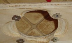
I have often seen the 'daisy' pattern on the rear of the cutout where rather than making a smooth chamfer around the rear, the four corners where the driver is attached are not chamfered.
So either the router has to be carefully maneuvered to create the pattern or hand filing is required.
Can someone bring in here a picture of that?
On my test box, I attempted to do this maneuver but I found that
my sweep was too wide or something so those corners still lacked
a good piece of the back to attach t-nuts. Maybe there is more control with a rasp. But it is a tedious technique. Besides I don't have a good half round file.
Also the chamfering bit I have is not the full dimension of the
usual router bits one sees for sale. It is considerably smaller has no guide bearing, just a stop at the base.
Seems like using a router would require either a steady hand or template, i.e. more trouble than it's worth unless in a small company production app, so I always used a coarse rasp since it's quick and all the groove irregularity is either acoustically transparent to lower BW or acts as a diffuser with HF.
Not a photo of my work, but similar, though it appears one side might not be gouged out enough:
GM
Not a photo of my work, but similar, though it appears one side might not be gouged out enough:
GM
Attachments
loninappleton said:Maybe there is more control with a rasp. But it is a tedious technique. Besides I don't have a good half round file.
I won't comment on the desirability of chamfering- it does seem to be a bit of a trade-off, since the rigidity of the driver attachment is reduced.
However, for tools to do the job:
For hand work something like the Microplane tools are quite effective- I've used them for guitar necks and the like. They also make a drum version for an electric drill.
A decent rasp is expensive.
Another surprisingly effective alternative is some very coarse sandpaper (sanding belt) wrapped around a curved (long) block. Think of it as a trip to the gym combined with a Zen exercise- the time will pass more quickly!
And, if you have them on hand, sanding drums in electric drills or coarse sanding disks in a hand grinder can also make this job go quickly.
Cheers
John
Yes. Better than my description and I've seen some nice hand-cut work to do this.
A work up such a jig or combination of bit and guide bearings would be interesting.
Or even just hog out a portion and then shape with a rasp.
I avoid buying things all the time.
Now with the new router I may see that I have more control with the
addition of a light on the device itself.
One thing I tried was to use a marker to paint on the pattern. But I overshot it anyway.

More on topic for you GM: I may have to decrease the CSA a bit so my
side pieces fit. And options for top and bottom should be bolt on rather than through the side panels. Originally I had in mind to have the front back top and bottom on the interior and sides outside the dimension. To get closer to the volume I should keep the top and bottom outside the dimension as well
It brings up another router question: some trim I have on the side pieces-- quarter round-- should have a top with the same radius work on the corners.
I've seen the use of a guide pin to steady a "work and turn" on the table but I have no clue how to perform the maneuver. I have made a table setup for the router but no fence yet or other niceties.
Today I may get to make another sample cutout in scrap if I get the trammel done.
A work up such a jig or combination of bit and guide bearings would be interesting.
Or even just hog out a portion and then shape with a rasp.
I avoid buying things all the time.
Now with the new router I may see that I have more control with the
addition of a light on the device itself.
One thing I tried was to use a marker to paint on the pattern. But I overshot it anyway.
More on topic for you GM: I may have to decrease the CSA a bit so my
side pieces fit. And options for top and bottom should be bolt on rather than through the side panels. Originally I had in mind to have the front back top and bottom on the interior and sides outside the dimension. To get closer to the volume I should keep the top and bottom outside the dimension as well
It brings up another router question: some trim I have on the side pieces-- quarter round-- should have a top with the same radius work on the corners.
I've seen the use of a guide pin to steady a "work and turn" on the table but I have no clue how to perform the maneuver. I have made a table setup for the router but no fence yet or other niceties.
Today I may get to make another sample cutout in scrap if I get the trammel done.
Having not seen the Sears Circle cutter I will have to acxknowledge Bill Hyltons trammel as one of the few alternatives-- in other words, make it.
You see, the pin position needed is right under the base of the router.
Hylton's trammel has a sliding mechanism which travls down to nearly zero clearance of the bit. I know of no pictures of his device.
However it is on the cover of Router Magic:
http://product.half.ebay.com/Router-Magic_W0QQprZ581421QQtgZinfo
As you can see, it's a pretty snappy device.
Delays and slowdowns are part of the learning process.
I'm going to go drage the book out of the library again.
Giving myself time to think
There may be a workaround for doing this cut. I noticed that the
unused holes (ones not used for the triangle pattern of the screws that hold the base on) might work. If it has to be a bit bigger or smaller I have a variety of straight bits.
Stay tuned.
There may be a workaround for doing this cut. I noticed that the
unused holes (ones not used for the triangle pattern of the screws that hold the base on) might work. If it has to be a bit bigger or smaller I have a variety of straight bits.
Stay tuned.
loninappleton said:
I've seen the use of a guide pin to steady a "work and turn" on the table but I have no clue how to perform the maneuver.
Do you mean how a circle or round over is shaped with a stationary router? http://www.diynetwork.com/diy/ww_decorative_furnishings/article/0,,DIY_14441_2276252,00.html
GM
My side panels have 1/4 round trim. So the top edge is flat.
The goal would be to make caps top and bottom with simple
radiused corners. Or something close. My builds are not fine furniture.
Making he caps a little oversize might make a nice pedestal look.
Otherwise flush to sides.
As noted, I'm slowed down by the circle cut. After a few samples if it isn't coming together I may go back to the rototoll.
Between time here I looked up the Sears alternate base. The comment from users was not good. It sounded like the same problem I have with the harness on the roto tool being loose is a problem with that one also. Plus that too did not look like it could get inside the base plate dimension.
I feel ike Goldilocks
Trial and error continues but I think I found a straight bit that is just right.
Above there I was wondering if using one of the machinings in the router base with a pin would give me the right diameter.
I started out with bigs and went down to littles. The littlest one is real close for the 144 mm measurement. I'm doing all this on a test piece.
In the broad view what this means is that after the hole is cut on the test and I find that I need that rabbet so the gasket seats properly I can do that as well from the opposite side *first* and then do the through cut on the final finished baffle.
I think I am done doing test cuts and working up the moxie to commit to the final surface cut and then do the rest of the through hole
from the back side.
Surface cut using 3/4 straight bit.,
Through cut using 1/8 in straight bit.
That produces the needed rabbet so the driver fits flat on the baffle.
I'm reviewing the dimensions so as not to mix and match all the discussion above.
My front baffle is 11.25" wide x 36 in long. The baffle is hardbood laminated with particle board and the thickness is 13/16.
Sides are 36" glueup butcherblock style shelving 12.5 (scant) wide and 3/4 in thick.
My mark for the cutout is 15" down.
Sorting out the port issues, GM has given an initial port diameter of 3".
and length 1.5 or so. I haven't cut any of that yet.
Of note, I did go back to the audioXpress magazine with the 167e build in it. The guy made the Fostex suggested build with a small cabinet.
The interesting thing is that he used some stuffing from McMaster-Carr called F-13 grey felt. I won't be doing any special ordering from them. But I will follow the guidelines that Scott had above there for his MLTL: top, back and one parallel side down to the driver. I just reviewd the whole thread.
www.mcmaster.com
Any last minute corrections?
Between time, I am going to practice making those hand cut chamfers with a file on one of my practice pieces. I may have to spring for a full size chamfer bit with guide bearing, but I'm putting that off too.
Still twiddling
I have to go back to my cutter for some final trimming of the baffle and back to fit the 3 ft. lengthof my reused side panels.
While thinking about this and rereading the thread, I'm still not sure
of the driver position on a 3 ft. length. At 15" down it is more than 1/3
the whole length.
The way the pieces look from the dimensions above, the shape of the CSA will be nearly square. That can't be helped with the useable pieces I have.
As a proportion of the whole front baffle, 12" down makes more sense.
GM, if you are back a confirmation would be helpful.
Again, the way I calc driver position is a function of both CSA and path-length ('L') to minimize damping required, so for a given 'L', the > CSA is, the further down the pipe the driver location. If you want to use a location higher up, then the worse case scenario is it will need more damping to smooth it out.
Again, not having ever done an in-depth measuring/listening comparison between mine and others higher pipe gain BW 'FR' driver alignments I can't say for sure that there's enough audible difference for it to be an issue, but I'm a believer that 'God' is in the details, so if enough minor details are addressed they will add up to an audible improvement. For all I know, theirs is superior, but IME 'less is more' where adding damping is required, so until I'm convinced otherwise I'm going to continue to recommend my way. 🙂
GM
I believe your judgment is good. I was just confused.
15" down on the length of 36" it is then.
When I laminated the hardboard to the particle board ti is
in the raw dimension of the particle board shelving which 11 1/4
All this stuff I am preparing to take to my cutter once the finals are
done.
Hopefully this will complete the final measures and I will be less tedious and repetitive:
11" wide x 36 in. long x 11" deep all inside dimensions. the only way I could get additional depth would be to scarf on a piece. Hopefully this TL in a square shape will be ok.
This piece will be real heavy and difficult to hoist about but I'm hoping the effort will be worth it. The bottom firing port will be about 20" from the floor on a stand mount as I've done previously.
Still not able to find a wool felt locally.
- Status
- Not open for further replies.
- Home
- Loudspeakers
- Full Range
- Box variations on the MLTL for the Fostex FE167e