Also Just Checked if it computes it does but the output still rly wrong because the LEM model is not considering any horn.
And also some other stuff I have to check but Computing time for now is quite ok

And also some other stuff I have to check but Computing time for now is quite ok
Well I have 0% sucessful experience witk AKABAK, tried simulating some HF waveguides in the past with not so good results 🙂
BTW sorry for all screw holes in 3D model
If we figure out step by step how to accurately simulate those cabs that would help me to make other designs too. Idea and 3D modeling is super easy for me but I always get stuck on simulations and wondering if design is even optimal.
BTW sorry for all screw holes in 3D model
If we figure out step by step how to accurately simulate those cabs that would help me to make other designs too. Idea and 3D modeling is super easy for me but I always get stuck on simulations and wondering if design is even optimal.
Yea AKABAK can be at times a bit fiddly but it can work very well. The only feasable and best approach for this type of sub I guess will be to go back and forth between real world messurments and optimizing the model untill we get simmilar results because I don't quite know yet how the horn mouth especially should be parameterized in LEM.
If we are able to recreate your current design in the model we can from there start to modify the current design and see how to improve it further.
But as Tom Danley already mentioned on a forum about the BC is that it will only give us a well informed guess but at the end we have to prototype it I guess.
And if we want to work on minimizing distortion caused by turbolance inside the horn we would need to work with a FIM modeling ofcause which AKABAK can't do.
Your measurements indicate the enclosures are working as Vermond's simulation models predicted, and a pair are very close to the DSL BC218 response, other than the choice to move the FC up a few Hz for more output.If we figure out step by step how to accurately simulate those cabs that would help me to make other designs too. Idea and 3D modeling is super easy for me but I always get stuck on simulations and wondering if design is even optimal.
The box is based on a Danley design, he generally does a very good job of optimizing them before putting products into production 😉 .If we are able to recreate your current design in the model we can from there start to modify the current design and see how to improve it further.
Art

Yea for sure he usually refines his designs before releasing any product or design. Some products he also optimized over the years after initial production. Often seen in his new iterations of old designs.
I reference Tom Danleys post on here talking about the Boundary compliment designs and talking how he uses AKABAK with extensive prototyping and validation using real life messurments due to the limitations of the Modeling alone for his designs to put my comment into context 🙂
https://www.diyaudio.com/forums/subwoofers/263812-danley-bc-subs-reverse-engineered-post4104201.html
Last edited:
Hey @All_1 !
First off: Thank you, and all the other people that have contributed, for the development of this epic build.
I'm going to build some, but will be making a couple small adjustments to make it fit my needs better.
I'm going to change the location of the NL4 connections. I want to move it to the "backside" whereas in your design they are on the side.


Considering I want to be able to set them up side-by-side, the connection of one sub would end up in the mouth of the one next to it.

Behold my epic paint skills! Only that I will start with just 4 subs, so only the top row.
Your placement prevents this kind of array, kind of forcing you to go for a split setup like you showed in post #180.
As far as I can reason, this places the centers quite far apart essentially creating a L-R sub setup, which results in comb filtering.
What was your reasoning for putting it where you did? (If my reasoning is faulty, feel free to point it out! )
I also want to add some sunken cutouts on the back for wheelplates. This way I can roll the subs around, but remove the wheels for a tighter packing in the van, and the prevent any rattling during shows.

My idea would be to place the 2 plates on the left of my image a bit further from the edge. This would create an easier setup to tip them upright in the van or storage.
I see you added holes in the braces.

Why are there no extra holes in the big mouth brace? Would extra holes in this brace somehow impact performance?
I could see how maybe you don't want air leaking from the back to the front part of the mouth.
Last question: which rubber feet did you use?
I like that you provided some sunk cutouts to "lock" the subs in place when stacked.
PS: Belgium and Slovenia are not that far apart. A meetup to make a bigger stack is an option 😉
First off: Thank you, and all the other people that have contributed, for the development of this epic build.
I'm going to build some, but will be making a couple small adjustments to make it fit my needs better.
I'm going to change the location of the NL4 connections. I want to move it to the "backside" whereas in your design they are on the side.
Considering I want to be able to set them up side-by-side, the connection of one sub would end up in the mouth of the one next to it.
Behold my epic paint skills! Only that I will start with just 4 subs, so only the top row.
Your placement prevents this kind of array, kind of forcing you to go for a split setup like you showed in post #180.
As far as I can reason, this places the centers quite far apart essentially creating a L-R sub setup, which results in comb filtering.
What was your reasoning for putting it where you did? (If my reasoning is faulty, feel free to point it out! )
I also want to add some sunken cutouts on the back for wheelplates. This way I can roll the subs around, but remove the wheels for a tighter packing in the van, and the prevent any rattling during shows.
My idea would be to place the 2 plates on the left of my image a bit further from the edge. This would create an easier setup to tip them upright in the van or storage.
I see you added holes in the braces.
Why are there no extra holes in the big mouth brace? Would extra holes in this brace somehow impact performance?
I could see how maybe you don't want air leaking from the back to the front part of the mouth.
Last question: which rubber feet did you use?
I like that you provided some sunk cutouts to "lock" the subs in place when stacked.
PS: Belgium and Slovenia are not that far apart. A meetup to make a bigger stack is an option 😉
@Lendert hey, regarding the placement. You can check out the Danley simulation software its free to take a look its not 1-1 but the design should be simmilar enogh.
https://www.danleysoundlabs.com/products/direct-sound-system-modeling-software/
Otherwise you can also use EASE Files should be available:
https://www.danleysoundlabs.com/education-support/support/software-support/ease-files/
What you will have is a bit of a tradeoff. Both setup options work. At lower frequencies it obviously does not matter too much.
I think you want to use 2 Mouths if you like a wider coverage and don't mind the power vally but otherwise the one that you drawn up.
Nice thing is that both is possible of cause. Ideally you have Multiple Connection panels so you can stack them however you like 🙂
And Good Luck building! 🙂
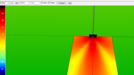
Here as an example (using averaged Levels) in the Danley software (dont got EASE atm installed on this PC):
2 Clusters in the 418 setup just now showing DBA:
@

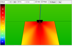
And here at 125hz with 1 octave for example:

In Comparison using your drawn setup:


https://www.danleysoundlabs.com/products/direct-sound-system-modeling-software/
Otherwise you can also use EASE Files should be available:
https://www.danleysoundlabs.com/education-support/support/software-support/ease-files/
What you will have is a bit of a tradeoff. Both setup options work. At lower frequencies it obviously does not matter too much.
I think you want to use 2 Mouths if you like a wider coverage and don't mind the power vally but otherwise the one that you drawn up.
Nice thing is that both is possible of cause. Ideally you have Multiple Connection panels so you can stack them however you like 🙂
And Good Luck building! 🙂
Here as an example (using averaged Levels) in the Danley software (dont got EASE atm installed on this PC):
2 Clusters in the 418 setup just now showing DBA:
@
And here at 125hz with 1 octave for example:
In Comparison using your drawn setup:
Attachments
Hey @All_1 !
First off: Thank you, and all the other people that have contributed, for the development of this epic build.
I'm going to build some, but will be making a couple small adjustments to make it fit my needs better.
I'm going to change the location of the NL4 connections. I want to move it to the "backside" whereas in your design they are on the side.
View attachment 1462843View attachment 1462844
Considering I want to be able to set them up side-by-side, the connection of one sub would end up in the mouth of the one next to it.
View attachment 1462845
Behold my epic paint skills! Only that I will start with just 4 subs, so only the top row.
Your placement prevents this kind of array, kind of forcing you to go for a split setup like you showed in post #180.
As far as I can reason, this places the centers quite far apart essentially creating a L-R sub setup, which results in comb filtering.
What was your reasoning for putting it where you did? (If my reasoning is faulty, feel free to point it out! )
You can ofcourse put them wherever you want them to be, probably both options would be ideal, so you have even more options and not be limited by it.
Yes, there are many improvements that could be made to help with mobility since is such a large (and heavy 🙂 ) cabinetI also want to add some sunken cutouts on the back for wheelplates. This way I can roll the subs around, but remove the wheels for a tighter packing in the van, and the prevent any rattling during shows.
View attachment 1462847
My idea would be to place the 2 plates on the left of my image a bit further from the edge. This would create an easier setup to tip them upright in the van or storage.
I see you added holes in the braces.
Holes would probably have minor impact on preformance (if any impact), there was not really a lot of thinking when I designed this brace, just that it fits properly. I like the look of solid brace a bit more and it's easier to clean. Holes would reduce weight tho.View attachment 1462846
Why are there no extra holes in the big mouth brace? Would extra holes in this brace somehow impact performance?
I could see how maybe you don't want air leaking from the back to the front part of the mouth.
Last question: which rubber feet did you use?
I like that you provided some sunk cutouts to "lock" the subs in place when stacked.
That is an option ofc 🙂PS: Belgium and Slovenia are not that far apart. A meetup to make a bigger stack is an option 😉
Remember this is purely DIY project and you can freely make any modifications. Rubber feet were 3d printed but we are moving to larger skids now. I reccomend you to make some carts for them anyways, we mostly transport 2 boxes already fixed together, super fast setup times.
First off, a MASSIVE thankyou to everyone involved with the creation of these beautiful designs. I've spent a lonnng time combing thru various subwoofer design threads and have seen some pretty wide-ranging levels of plan clarity, modelling/simulation, and build quality out there. This project is top shelf!
Will be starting to make sawdust next week after making a couple edits to the plans to suit our specific needs. (removed pressure sensor holes and the revetments for rubber feet). Adding plastic skids in a similar style to the Danley BC218 - asymmetrical placement with an adjacent channel to receive the skid from the opposing cabinet.
@All_1 - could you please advise where you obtained your skids? I'm not having much luck finding anything longer than 19". Once we find an appropriate option for this, we can finalize our CNC plans and start making sawdust 🙂
Will be sure to report back with build photos etc as it all comes together!
Yup, will be using 18SW115-8 drivers, with a Powersoft K10 running 2 cabs per channel. Just putting finishing touches on some slight adjustments to the CAD plans (different handles etc) and then will be getting started soon! Will keep updated as we go 🙂
- Home
- Loudspeakers
- Subwoofers
- Boundary control BC subwoofer BC218/2 Design