I did not mean to start a new thread. It was supposed to go into the original thread on the Boulder 990 line amplifier.
I find it interesting that the designer of the 990 used inductors in the tails of the differential pair for gain reduction at higher frequencies and find it even more interesting that there is a patent on this. After all the leads of the devices themselves in the differential pair could be considered to be a inductors. Thus a differential pair already has inductors due to the very nature of the devices themselves. Could adding a few high permeability ferrite beads to the device leads with a resistor across them be a infringement of the patent? You could get perhaps up to 20 to 30 micro henries this way.
I myself would not use added inductors in such a location since it will likely deteriorate the balance of the circuit at higher frequencies.
As far as the Boulder 993 diagram goes, I know nothing about it. But if I wanted it bad enough I would just buy a module and do some reverse engineering. But what is the point. Sure they look nice and appear to be made to plug into a console, but there are likely other circuits out there that will work just as well. Nobody has a sole option on performance. My advice is to design your own if you can. It gives much greater pleasure that copying someone elses work.
John Fassotte
Alaskan Audio
alaskanaudio said:
As far as the Boulder 993 diagram goes, I know nothing about it. But if I wanted it bad enough I would just buy a module and do some reverse engineering.
If the phono preamp goes for $35,000, you might expect to pay at least $1,000 for a module.😉 I don't even think it's that good.
Re: Re: Boulder 990 and 993 Diagram
I'm not sure what this reply to a partial quote means or how it relates to the 993. Can you explain further?
John Fassotte
Alaskan Audio
Peter Daniel said:
If the phono preamp goes for $35,000, you might expect to pay at least $1,000 for a module.😉 I don't even think it's that good.
I'm not sure what this reply to a partial quote means or how it relates to the 993. Can you explain further?
John Fassotte
Alaskan Audio
There is another thread about Boulder equipment and one member stated that phono unit sells for $35,000 in Germany. So I deduct that if somebody would like to buy a module for reverse engineering purposes, he might probably have to spend at least $1,000. Which brings the question: is it worht it?😉
Over priced
If that is the price it is definitely not worth it. Especially if you look at the printed circuit board pictures that have been posted. I doubt if there is more than $50.00 in parts on the board.
My curiosity is up however even though I don’t have a need to know. I will investigate the claims of the 993 more over next week or so.
Johannes Fassotte
Alaskan Audio
alaskanaudio said:I did not mean to start a new thread. It was supposed to go into the original thread on the Boulder 990 line amplifier.
I find it interesting that the designer of the 990 used inductors in the tails of the differential pair for gain reduction at higher frequencies and find it even more interesting that there is a patent on this. After all the leads of the devices themselves in the differential pair could be considered to be a inductors. Thus a differential pair already has inductors due to the very nature of the devices themselves. Could adding a few high permeability ferrite beads to the device leads with a resistor across them be a infringement of the patent? You could get perhaps up to 20 to 30 micro henries this way.
I myself would not use added inductors in such a location since it will likely deteriorate the balance of the circuit at higher frequencies.
As far as the Boulder 993 diagram goes, I know nothing about it. But if I wanted it bad enough I would just buy a module and do some reverse engineering. But what is the point. Sure they look nice and appear to be made to plug into a console, but there are likely other circuits out there that will work just as well. Nobody has a sole option on performance. My advice is to design your own if you can. It gives much greater pleasure that copying someone elses work.
John Fassotte
Alaskan Audio
John,
The technique using inductors in the LTP emittors is not very special, just another way to roll off gain at hf to avoid instability. The usual means (cap from c to b for instance) is just easier because of better availability of caps. If there was a patent on it it might be worthwhile to check the dates. I have a hunch that it would be expired
I fully agree to the last part of your statement!
Jan Didden
The Boulder phono stage IS very, very good. Setting issues of system compatibility and sonic preferences aside, it is probably among the 5 best phono stages that I have ever heard.
regards, jonathan carr
regards, jonathan carr
At the asking price, it is probably among five most expensive units as well, so it better sounds good.😉
So you say it is so good? That module must be doing something right then. I wonder why Harry wasn't impresed with a schematic?😉
So you say it is so good? That module must be doing something right then. I wonder why Harry wasn't impresed with a schematic?😉
Peter: I didn't find the schematic that has been posted here very interesting either, but who knows if that is what the current 2008 is using (Boulder's website does say of the 993 gain stage "newly designed").
As far I know, the 2008's remote power supply box (which runs fairly warm) contains an AC power regenerator system (don't know the operating frequency), which should give it a useful margin of independence from local AC powerline conditions. From experience, given good grounding and a clean powerline, my own Connoisseur 4.0 sounds better than the Boulder, but when there are grounding or AC powerline issues in the audio system environment, it is the Boulder that can sound better (I'll have to correct that the next time I do a revision, grin). So it appears as though the 2008's power supply system must be doing something right.
regards, jonathan carr
Jonathan,
I've just seen the pictures of your pramp and I'm not surprised it can sound better than Boulder. Tremendous attention to detail, something to inspire in my next project. I'm greatly impressed.
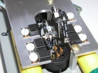
I also started doing my circuits in "3-dimensional air-dielectric construction" with the shortest signal path possible. Here is a sample of my attempt, almost no wires, preamp's circuit virtualy hangs on input and output jacks. When I see the layout Boulder style, somehow I can't imagine that this is the last word with a given circuit topology. Their components are also of average quality.
I've just seen the pictures of your pramp and I'm not surprised it can sound better than Boulder. Tremendous attention to detail, something to inspire in my next project. I'm greatly impressed.
I also started doing my circuits in "3-dimensional air-dielectric construction" with the shortest signal path possible. Here is a sample of my attempt, almost no wires, preamp's circuit virtualy hangs on input and output jacks. When I see the layout Boulder style, somehow I can't imagine that this is the last word with a given circuit topology. Their components are also of average quality.
Attachments
Sorry Peter Daniel
Sorry
My E-mail(12Mega byte free space)
I had received ml1.bmp ml2.bmp ml3.bmp .If you have other Schematic Please send to me
Thank you
Sorry
My E-mail(12Mega byte free space)
I had received ml1.bmp ml2.bmp ml3.bmp .If you have other Schematic Please send to me
Thank you
Peter: The "tent-style" resistor arrangement in your photo reminds me somewhat of what we were doing in an earlier product called the Connoisseur 2.0. If you are interested, I can email you a few closeup JPEGs of some of the boards that I built.
regards, jonathan carr (connlyra@gol.com)
regards, jonathan carr (connlyra@gol.com)
- Status
- Not open for further replies.
- Home
- Amplifiers
- Solid State
- Boulder 990 and 993 Diagram