Everything is more expensive over here, and the reason is “just because they can”. I bought several hundred of those multi turn pots from BG Micro before they went away at around 20 cents a pop. Hopefully enough that I don’t have to order any overpriced ones for a good long time.

Total Harmonic Distortion: 0.000373%(0.000000%)
R34 is just to reduce the offset from about 4mV to about 100uV since you seem to care? I wouldn't bother with less than 50mV. I tried to keep the idle current the same. I did not run the phase margin so you will want to check that. Note that the upper 3k3 is pointless if you parallel it with 680 Ohms.
R34 is just to reduce the offset from about 4mV to about 100uV since you seem to care? I wouldn't bother with less than 50mV. I tried to keep the idle current the same. I did not run the phase margin so you will want to check that. Note that the upper 3k3 is pointless if you parallel it with 680 Ohms.
Attachments
Bourns 1k 10-turn is $1.38 on sale from my trusted ham radio operator Ebay seller. Digikey = 3296W-1-103RLF = $2.66 !!
Nothing wrong with those $0.25 China trimmers . They include them with my little +/- 317/337 regulator kits.
Same with silver mica caps , I can get genuine 3-500V CDE SM's $9.00 for 30 pieces !!! NOS mica is just as good as Digikey's $2.42
genuine Silver caps.....
Some sellers , you can get cheap NOS (new old stock). I WON'T buy electrolytic caps like that. I need to know the date of manufacture
and test one for ESR at many frequencies. Compare to spec. Many electrolytic scammers in Florida/PR !
OS
You can also try matching the longtail pair carefully, but that is even more trouble. Are you doing this for production and need to make many and cut down on setting up cost.
Nico, this is my personal project, a replacement actually from a failed one, and exactly the same reason why I wanted a very low dc offset at least in sim because in the actual build that is not what you can expect to get as per sim. I am actually using a cheap speaker protection.Another way is varying the tail current slightly by adjusting the CCS up or down. Don't do this in simulation but on the bench, everything a simulator says is not gospel. Of course to eliminate any off-set is utilising an output capacitor, but that is even more expensive alternative. Does the off-set really bother you that much that you are worried to damage your speaker?
I could not actually say that my later diy build 'failed' it works but it sounded more like a headphone amp. I tried to fix it by fired it up in sim again but it turned out I have to omit some components to get it back as a working power up. I eventually gave up coz the board became useless.
I know of one person that may help me out correct the fault in the design, it was Henk (Hennady Kovalsky) I did most of the design and Henk suggested to add a few components. (but it seemed Henk left DIYAudio his profile is no longer found.)
Attachments

Last edited:
The circuit looks the same scheme like the one they are using to drive mosfet outputs.🤔Double boot strap. Allows the followers on both sides to go as rail to rail as they can, even if the input signal is a little shy of it. Not really applicable to the AX11.
Thanks Os, for your circuit 'samples.Wolverine does a trimmable virtual ground reference derived from the rails. I "stole" that from one of those 10K$ hand crafted
Thanks steveu, I will check your asc later tonight. Same thought with paralelling 680 to the upper 3k3 bootstrap more current shifts to 680.Total Harmonic Distortion: 0.000373%(0.000000%)
R34 is just to reduce the offset from about 4mV to about 100uV since you seem to care? I wouldn't bother with less than 50mV. I tried to keep the idle current the same. I did not run the phase margin so you will want to check that. Note that the upper 3k3 is pointless if you parallel it with 680 Ohms.
steveu, i made a quick check on your .asc file, while THD drops to a very low level but it loses a good amount of 2nd harmonic. Was it because of the added (2nd) VAS transistor?
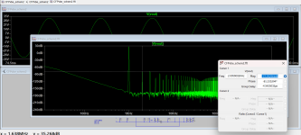
I think we may all agree to loose Q14, I am now presenting you 2 schematic for choosing. Schematic1 was the first and original, schematic 2 contains VAS helper (2nd transistor as propsed by member steveu). Now I am seeing two different patterns, I am showing the results for 1KHz FFt window, because the comparison here can be clearly seen. Both simulated with equal bias current the same input amplitude at the same output power level (63w) with both having 30dB of closed loop gain.
Notice the amount of harmonics on each window preferably the 2nd harmonic. Is there a correlation to loudness in the ouput sound of the amp on the level of harmonics?. Say the one with higher level of harmonics is much louder? While the schematic with the 2nd VAS transistor shows 000% THD but the measured dB is higher. Help me to decide which one would be a 'better one'.
Thank you!
Attachments

Last edited:
Anyone? set aside the schematic comparison. Just give me knowledge info on the FFT results. (shown above).
Thanks!
Thanks!
So I built the amp, but it is outputting the rail voltage (+37vdc) I have no idea why, my first encounter on such error. Any ideas where to check for fault?
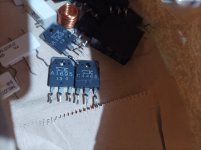
In the schematic I replaced the 2SC5200/SA1943 with Sankens. I happen to have 3 pairs of them (taken from an old amplifier). I am not so sure though if the replacement Sanken output transistors causes the trouble.
In the schematic I replaced the 2SC5200/SA1943 with Sankens. I happen to have 3 pairs of them (taken from an old amplifier). I am not so sure though if the replacement Sanken output transistors causes the trouble.
Attachments

Sorry for the joke, I have just never seen a clothes iron for heat sink! Are you married, I hope not! Your wife will beat you over the head if she sees what you have done.
Hi Nico,If the problem was not there before using the Sankens, then you know where to look.
Is it biased in class A? That is why you will use it as a clothes iron? 🤣
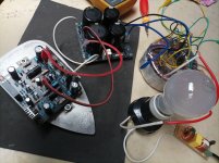
The Sankens was there the first time I powered on the amp. The flat iron plate looks pretty good for a test hsink for an amp with about 25ma - 50ma bias current, easier to drill holes and is made of pure aluminum. I think member Borys also used flat iron plates on his amp tests.
I'm 53yrs old, married of course 🙂 wifey won't care about the flat iron plate as long as the flat iron in the house is in place 😁, but she will be delighted if this amp will sing beautifully. She loves music, the type of Bee Gees, we are the opposites as I'm more on the rock/metal stuff, from the likes of Led Zep - Alice in Chains - Dream Theater. I was born in the silicon age 😄 that is why I am passionate about building class AB amps.Sorry for the joke, I have just never seen a clothes iron for heat sink! Are you married, I hope not! Your wife will beat you over the head if she sees what you have done.
Last edited:
...built the second channel following the original schematic using 2SC5200/SA1943 for the outputs. Surprisingly the same error occured, both channels had identical errors. They both have DC voltages (rail voltage) on the speaker out. Judging from both scenario I suspect that the fault could possibly lie in the circuit design. I'm thinking that if the fault lies in the PCB, chances are the amp will self oscillate and or a shortage may occur, but at power on the lamp bulb will flash momentarily then the brightness slowly goes away. Pretty normal I guess for a PSU with a cap banks of 40,000uf.
I actually made a few component adjustment for my last attempt of testing for the day but at power on, still the same error occurs. This is going to be one tough job and can be really frustrating.
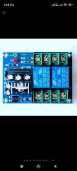
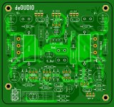
I am attaching the latest schematic with the adjustments that I made and also the PCB photoview for you to check if there are errors made with the routing of tracks.
Thanks you all!
I actually made a few component adjustment for my last attempt of testing for the day but at power on, still the same error occurs. This is going to be one tough job and can be really frustrating.
I am attaching the latest schematic with the adjustments that I made and also the PCB photoview for you to check if there are errors made with the routing of tracks.
Thanks you all!
Attachments
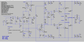

The amp looks pretty normal and the simulation says that it does work. According to the simulation both output currents are the same so the output voltage is at zero. There is no indication that the schematic is incorrect in a way that you describe. Are you sure that you have not got a transistor wrong way round somewhere. You cannot always believe the silkscreen.
It looks like you are using MicroCAP simulator. Turn on the voltage display and probe you circuit to see if it corresponds to the simulator. Maybe just start with checking the output and driver transistors E/C junction for a short. Did you use the specified components, not that Q1 and Q2 pinout is different that the other transistors, so you cannot put anything in its place.
I'm using LTSpice, all the components that I've used are brand new (well mostly except maybe for the small filter caps on board) but of course most of them are China made. For the transistors I made a quick analog test for their BCE junctions, they look fine to me except maybe one or a few failed while in circuit. I will double check my work again and compare the component placement per the PCB and schematic.
I wish I still have my MicroCAP installed in my laptop. From experience MicroCAP accurately outputs currents and voltages than LTSpice. I am getting older 😆 my eyes hurts when doing soldering and desoldering stuff.
Thanks Nico!
I wish I still have my MicroCAP installed in my laptop. From experience MicroCAP accurately outputs currents and voltages than LTSpice. I am getting older 😆 my eyes hurts when doing soldering and desoldering stuff.
Thanks Nico!
I checked your PCB as well as I could and don't see any mistakes. Can you also check the two protection diodes if there might a short across it. I notice all MC12 sites are down or has other rubbish attached. I have the completer zipped file but is 59MB but cannot attach it here. Maybe DIYaudio could create an archive to dump all the useful software packages into for everyone to access.
- Home
- Amplifiers
- Solid State
- Bootstrapped CFP in the making