Hello,
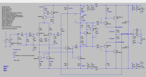
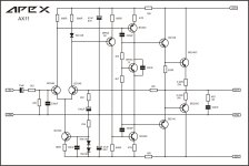
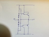
In the course of my sim rerun of my old circuits I was surprised when I find out that the extra transistor on ltp input found on AX series amp of Apex works well in balancing the currents and voltages of this bootstrapped CFP that I have drafted. The only problem that I found was that the lower resistor 3k3 (R14) receives about 300mW. The upper resistor 3k3 (R13) current was halved sharing with 680r (R31) tied on the collector of Q14.
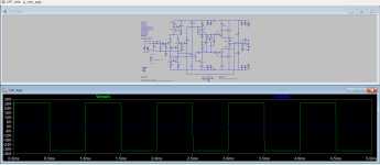
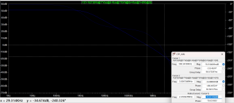
AC analysis, transient response, square wave (1khz) shows good results. RC network 330p/470 tied at the legs of the ltp is optional. The scheme gives a good amount of ULGF and gain margin in exhange for dropping a few phase margin and some overshoots in the square wave test for the higher frequencies, but without it the circuit displays a fair amount of gain margin of -16 to -17dB and with about -77° of phase margin.
I actually created the pcb lay-out and thinking of revising it but I have decided to put a hold on it at the moment. I wanted to ask you if the additional extra transistor (Q14) will actually work. (without putting R14 in smoke of course 🙂). By the way it doesn't work without the current mirrors. I have simulated a few bootstrapped amps and most of them does not show a good balance of voltages on the output Re's. The lower minus rail always has an extra voltage of about 2mv higher from the upper plus rail. ( referring to measured voltages across each output re 0.22r, plus side vs minus side). And yes I am preserving the bootstrap 'ala' P3A 😉.
I have attached the ltspice files for you to check on (models included).
I appreciate any feedback. Thank You!
In the course of my sim rerun of my old circuits I was surprised when I find out that the extra transistor on ltp input found on AX series amp of Apex works well in balancing the currents and voltages of this bootstrapped CFP that I have drafted. The only problem that I found was that the lower resistor 3k3 (R14) receives about 300mW. The upper resistor 3k3 (R13) current was halved sharing with 680r (R31) tied on the collector of Q14.
AC analysis, transient response, square wave (1khz) shows good results. RC network 330p/470 tied at the legs of the ltp is optional. The scheme gives a good amount of ULGF and gain margin in exhange for dropping a few phase margin and some overshoots in the square wave test for the higher frequencies, but without it the circuit displays a fair amount of gain margin of -16 to -17dB and with about -77° of phase margin.
I actually created the pcb lay-out and thinking of revising it but I have decided to put a hold on it at the moment. I wanted to ask you if the additional extra transistor (Q14) will actually work. (without putting R14 in smoke of course 🙂). By the way it doesn't work without the current mirrors. I have simulated a few bootstrapped amps and most of them does not show a good balance of voltages on the output Re's. The lower minus rail always has an extra voltage of about 2mv higher from the upper plus rail. ( referring to measured voltages across each output re 0.22r, plus side vs minus side). And yes I am preserving the bootstrap 'ala' P3A 😉.
I have attached the ltspice files for you to check on (models included).
I appreciate any feedback. Thank You!
Attachments
Last edited:
CFP is a bit of trouble for stability.
With bootstrap maybe asking for trouble.
The diff pair is nice , little degen helps.
Looking at the overall extra compensation.
from C7 R33 and high value of C5
looks like a little arm wrestle to get going.
Maybe 3ma to high specially with current mirror.
Might be able to bring it down to 2ma
or even 1ma with KSA992
3ma might be unstable.
Or less compensation would be needed.
degen might go up to 180 to 220 ohms

True, my first build oscillated the first time.CFP is a bit of trouble for stability
I opted for 100p/330r maybe a good balance for C5. Gain margin is at -16dB.Looking at the overall extra compensation.
from C7 R33 and high value of C5
looks like a little arm wrestle to get going.
Lower value degens and higher value for the current mirrors seemed to work also.degen might go up to 180 to 220 ohms
There is some uniqueness in bootstrap scheme with CFP outputs it sounded more 'robust' like a big amp. My first CFP was P3A and it sounded really good it also reminds me of the VSSA, small amp with huge soundstage.With bootstrap maybe asking for trouble.
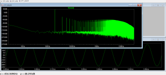
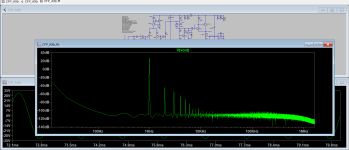
Here's the revised schematic I split R14 in halves so each resistor (with R34) will share the power dissipated and hopefully will prevent it from heating up. I'm not so sure if this is a good idea though, it worked in the sim. The FFt windowing shows a good amount of H2, I used Hann. I do not know how to optimize it to show a flat noise floor.
Attachments

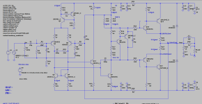
Since the current mirror isn’t there anymore, I’m not sure Q14 Is doing anyone any good. It is normally there to turn a VAS into push pull instead of CCS loading. A boot strap is a poor man’s CCS, which actually works quite well in its normal implementation. There is a push pull analog of the boot strap, but it’s center driven not referenced to a rail, and has two bootstraps.
In simulation the only noticeable thing that Q14 does is keeping the currents and voltages of the outputs Re. pretty much balanced and in check plus a very low dc offset. I tried omitting the current mirrors and keeping Q14 but it does not work. Currents and voltages went astray, maybe because of the bootstrap but with AX11 it works fine.
Do you have a circuit example?. There is a push pull analog of the boot strap, but it’s center driven not referenced to a rail, and has two bootstraps.
Yes, thank you but I do not want additional trimmers. I would prefer to work on zeroing the dc offset (if it cn be done) without the aid of trimmers.Zero output off-set adjustment
Of course it can be done, op-amp and auto zero but that is complex more so that turning a small trimmer pot and then forget about it.
Another way is varying the tail current slightly by adjusting the CCS up or down. Don't do this in simulation but on the bench, everything a simulator says is not gospel. Of course to eliminate any off-set is utilising an output capacitor, but that is even more expensive alternative. Does the off-set really bother you that much that you are worried to damage your speaker?
Double boot strap. Allows the followers on both sides to go as rail to rail as they can, even if the input signal is a little shy of it. Not really applicable to the AX11.Do you have a circuit example?
Attachments
In order to strictly enforce differential balance with a single ended VAS with a resistive load, something needs to be trimmable. With real CCS’s in the collector and the tail, one can hand select matched resistors to enforce current balance, once values and a matched input pair have been selected.
This is one reason more advanced circuit topologies can sound better than the vintage ones. A poor choice of collector resistor or change in supply voltage, and the input pair can go so far out of balance that an old school singleton and temp comp diode would do better.
This is one reason more advanced circuit topologies can sound better than the vintage ones. A poor choice of collector resistor or change in supply voltage, and the input pair can go so far out of balance that an old school singleton and temp comp diode would do better.
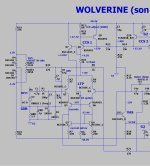
Wolverine does a trimmable virtual ground reference derived from the rails. I "stole" that from one of those 10K$ hand crafted
Nikko's 😉. Differential balance can be real anal , that's important to get sub PPM.
I personally use servo controlled CCS's on my favorite symmetrical designs - uV offsets rule.
OS
Nikko's 😉. Differential balance can be real anal , that's important to get sub PPM.
I personally use servo controlled CCS's on my favorite symmetrical designs - uV offsets rule.
OS
Attachments
What is wrong with trimpot. It is much simpler than any of the other suggestions and you would probably trim it once in your life.
Old (non sealed) trimmers can fail . Careful design , or HQ sealed trimmers can minimize a fault to a degree.
I get scared of a badly designed bias trimmer (Vbe) that defaults to high bias. I've seen this on cheap OEM's.
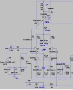
What would happen to the post #7 circuit with a failed trimmer ?
(below circuit) A failed trimmer R9a/b here , R7/8 would save the day. Just higher Re - and a little more offset.
OS
I get scared of a badly designed bias trimmer (Vbe) that defaults to high bias. I've seen this on cheap OEM's.
What would happen to the post #7 circuit with a failed trimmer ?
(below circuit) A failed trimmer R9a/b here , R7/8 would save the day. Just higher Re - and a little more offset.
OS
Attachments
Is there no good trimmers in your country. That is terrible. This one is about 0.20 USD Put it on the side so it fails low bias. Need some help with it?

We have those , but 1-2$. I use those bourns , many a OEM does not.
I have seen these fail , but it's rare.
Edit , that must be a China knockoff for .20c , Bourns go for 1$ +++.
I have seen these fail , but it's rare.
Edit , that must be a China knockoff for .20c , Bourns go for 1$ +++.
Actual Bourns might be 20 cents there. I’ll bet generic viagra is. Could be a second tier brand too, maybe not good for nV offset trimming but fine for what we’re doing.
- Home
- Amplifiers
- Solid State
- Bootstrapped CFP in the making