If anybody has bought such a HV boost converter (or similar from other vendors) or knows the answer:
High Voltage DC DC Boost Converter 8 32V to 45V 390V ZVS Capacitor Charging free shipping -in Integrated Circuits from Electronic Components & Supplies on Aliexpress.com | Alibaba Group
What puzzles me about the +/- output version:
- how can a non-isolated boost converter produce both, a positive AND a negative voltage ?
- boost has only an inductor and can only boost one polarity !
- unless it is actually a flyback with transformer secondary center tapped ...
- but then, why non-isolated ?
Attachments
why don't you buy one and reverse engineer it?
i suspect flyback and the controller tied to one half of the bifilar secondary's makes it DC-DC
good luck finding the controller #, somebody said they sanded the tops.
I would subscribe to your findings.
i suspect flyback and the controller tied to one half of the bifilar secondary's makes it DC-DC
good luck finding the controller #, somebody said they sanded the tops.
I would subscribe to your findings.
A single inductor can boost dual polarities. I'm thinking of a circuit in the LT1110 datasheet, iirc. How relevant here... I wouldn't wager much.
A single inductor can boost dual polarities. I'm thinking of a circuit in the LT1110 datasheet, iirc. How relevant here... I wouldn't wager much.
O.K. the negative in the LT1110 app is via a charge pump, connected before the rectifier; needs three HV caps, but the item in question has just two ...
I have bought a pair. I can check them for you if you can wait until weekend when i get home.
good, I had hoped for somebody to have already bought one ... look forward to seeing your findings, thanks.
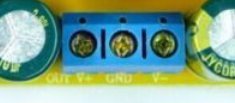
As requested.
You can check the high resolution pics by clicking the images below.
I happen to have a pair of this module so i posted a picture with them mirrored.
http://minus.com/i/LcmWN7d9pNyf
http://minus.com/i/mm7DzvLT1ldD
Yes, the controller ID has been sanded-off. The secondary winding seems centertapped with each end connected half wave rectified by ultra fast diode. One end makes the positive and the other end makes the negative, hence bipolar.
Unfortunately i don't know enough about SMPS to comment more. I do agree it seems this is flyback type. One end of the primary winding goes to the center pin of the heatsinked MOSFET.
I will be bringing this module with me for the week, so if you have any more question, i can help to check it. Do share any findings.
You can check the high resolution pics by clicking the images below.
I happen to have a pair of this module so i posted a picture with them mirrored.
http://minus.com/i/LcmWN7d9pNyf
An externally hosted image should be here but it was not working when we last tested it.
http://minus.com/i/mm7DzvLT1ldD
An externally hosted image should be here but it was not working when we last tested it.
Yes, the controller ID has been sanded-off. The secondary winding seems centertapped with each end connected half wave rectified by ultra fast diode. One end makes the positive and the other end makes the negative, hence bipolar.
Unfortunately i don't know enough about SMPS to comment more. I do agree it seems this is flyback type. One end of the primary winding goes to the center pin of the heatsinked MOSFET.
I will be bringing this module with me for the week, so if you have any more question, i can help to check it. Do share any findings.
Last edited:
TY ballpencil
standard cheep-n-nasty id say
any plans to power them up with an Oscope handy? ZVS uh I dont think so
standard cheep-n-nasty id say
any plans to power them up with an Oscope handy? ZVS uh I dont think so
I have only a pocket oscope.. the DSO203 Quad.. Do you think it's precise enough to see the output of an SMPS?
DSO Quad - Wiki
Can you tell me what is wrong with ZVS capacitor charger circuit? Low switching frequency?
DSO Quad - Wiki
Can you tell me what is wrong with ZVS capacitor charger circuit? Low switching frequency?
I have only a pocket oscope.. the DSO203 Quad.. Do you think it's precise enough to see the output of an SMPS?
DSO Quad - Wiki
Can you tell me what is wrong with ZVS capacitor charger circuit? Low switching frequency?
IDK I guess it works fine if your building an electric fence of or a zapper thingy.
your 'scope' is not a tool id pick to characterize HV SMPS, it could be used but would take advanced thoughts of what to look for! a double minus for most DIY folks I reckon. some models are limited to 60V.
OTOH for audio if you cant hear it nor see it, it'll do, if it causes grief, it might take some more work and $
Last edited:
@ballpencil: thanks for the pictures;
I'm pretty shure now it's flyback; ct of secondary connected to gnd of input for easy regulation feedback (isolation would require opto-coupler for fb)
btw there is also a single voltage version available from multiple vendors, some as low as $7.
I'm pretty shure now it's flyback; ct of secondary connected to gnd of input for easy regulation feedback (isolation would require opto-coupler for fb)
btw there is also a single voltage version available from multiple vendors, some as low as $7.
- Status
- Not open for further replies.
- Home
- Amplifiers
- Power Supplies
- Boost Converter w/ positive AND negative output