I've been grappling with gain staging calculation a lot lately. I think I'm finally getting the hang of it, so please take whatever I write here with a grain of salt. ANYBODY LOOKING AT THIS -- Please correct me on anything you see below!
---
So here's my proposal...
With only 300V of B+ available, you won't get much power out of a pair of 6L6's. You'll definitely want to run them as pentodes (or in ultralinear if your output transmformers have screen taps). But then again, with that low a B+ available and with the current limitations of your power transformer, you'll get little more power from a pair of 6L6's than you will from a pair of 6V6's. So why use the bigger tubes?
The good thing about using 6V6's is that they will be really easy to drive. You won't need a current-hungry, high voltage driver stage to get them to full power. You'd actually be able to use a single long-tailed pair phase splitter like in Eli's El Cheapo amp (which basically uses a 12V, 7-pin version of the 6V6 in its output stage). Since you already have four small signal tube sockets, you could use a pentode for the constant current source in the LTP phase splitter cathodes. That would be a very high performance option.
With 300V of B+, I'd expect the bias on a pair of 6V6's to be about -15 volts or so (not sure exactly). I got 21x gain from a 12AT7 LTP phase splitter, so if you can get the 12AT7 running with a bias of about -1.7V or higher, you will have all the headroom necessary to put a little feedback around the circuit. (6dB of NFB requires double the drive voltage).
So, working from the output tubes to the input of the circuit:
- 6V6 with -15V bias means 15V peak (30V peak-to-peak) will drive the output stage to full power
- the 12AT7 will need to deliver at least 15V peak, and more for negative feedback (which reduces the input sensitivity of the stage with the feedback entering it).
- The 12AT7 has a published gain spec (mu) of about 60. In an LTP with single-ended input, you'll get only half that, so 30. There will be losses with resistors as plate loads, so figure on a final gain of 21 or so.
- The input voltage to the 12AT7 cannot exceed its Vgk (bias voltage). Figuring on a Vgk of 1.5V, that means you can get about 1.25V peak signal into it before it starts distorting. 21 x 1.25 = 26.25 -- Which is enough for about 5dB of NFB.
If you use 6L6 with these same conditions, you'll need a few more volts of grid bias (probably -18V) and you won't get hardly any more power. That means you won't have the voltage gain available from the 12AT7 for feedback. Also, 6V6GT's sound really nice.
If you use the "Mullard" style circuit you've posted, you'll have waaaay too much gain unless you put a lot of negative feedback around the circuit to reduce the gain to something usable. Then you'll need to work on getting the circuit stable, make sure the OPT's don't ring, etc. But that's good too.
I like Eli's idea of using a two-stage, LTP to PP, and use the extra tube sockets for pentode CCS's for the LTP's. You might even be able to use 6DJ8's for that.
--
Again, please check all that, and if anybody has corrections, please post 'em. I'm hoping to learn as I go along.
Thanks, and I hope this helps.
--
My OPTs are 3,600 primary. The 6V6 does not look very happy with this.
I like the pentode CCS option. I was reading an article the other day about CCS loading a Phase inverter with a pentode and thought it looked pretty nice!
Blair
I like the pentode CCS option. I was reading an article the other day about CCS loading a Phase inverter with a pentode and thought it looked pretty nice!
Blair
My OPTs are 3,600 primary. The 6V6 does not look very happy with this.
Oh, I missed that. You're right about that. 3k6 is low even for 6L6.
Do you know what the max current capability is for your power transformer? One thing that works well is to run the 6L6's (or even EL34's) at a low plate voltage but high plate current. You don't get much power, but you can get the distortion low.
The Russian 6P3S (what Sovtek sells as their cheapest "6L6GC") is only rated for 20 watts max plate dissipation. You could run it at 300V on the plate, 65mA plate current per 6L6. You could run the screens from a lower voltage regulated supply (like 250V), again to lower distortion.
But all that assumes that your power transformer has enough current capacity.
--
Hi Rongon,
That was my plan. I'm not exactly sure what the tranny is rated for, but the receiver had 23 tubes. 4 7355s, and an assortment of other 7-9pin variants. So, I'm looking at 4 X 6l6s, and 4 tubes of my selection.
Assuming I do not choose any current hogs, I would assume I should have decent amount of current.
How about this?
You mentioned the Mullard topology having too much gain. What if I use a 12AU7 as the driver, and either a 6CG7 or 12AU7 as the PI? That should tame a little of the gain right?
I found a data sheet with the 6l6 running at 270v into 5k at 17W. I figure I can get around the same power, but possibly bias it down a bit due to the lower transformer load.
Thanks!
Blair
Maybe triode strap output tubes (6V6GT or better EL84/6BQ5 ) run in parallel for a 7.2K primary impedance. Also EL34 triode strapped too may take 3.6K better. Fixed bias should be used for best results too!
Randy
Randy
Hi Randy,
I do not have enough heater current to go EL34 triode, or that is exactly where I would be🙂 I love EL34 in triode.
I really expected a different PP primary out of these closer to 5-6k.
Blair
I do not have enough heater current to go EL34 triode, or that is exactly where I would be🙂 I love EL34 in triode.
I really expected a different PP primary out of these closer to 5-6k.
Blair
Get Heater supply transformer as they can be had for low cost. Antek may have something suitable.
6CW5/EL86 is another choice, but PS trans would have to be changed.
Tubes & Transformers
Randy
6CW5/EL86 is another choice, but PS trans would have to be changed.
Tubes & Transformers
Randy
Hi Randy,
I would do that if I had the real estate to add another transformer. I'm kind of stuck on this one.
Blair
I would do that if I had the real estate to add another transformer. I'm kind of stuck on this one.
Blair
Last edited:
Maybe put the PS transformers (and choke if used or leave room for a good one later ) on a small separate chassis or make mono-blocks for better stereo separation, sound stage etc.
Last edited:
deicide67,
I expect that since you have four octal sockets for output tubes and four 9-pin mini sockets for driver tubes already mounted in the chassis, that you want to use those?
I don't see where you could stuff four more octal sockets for push-pull-parallel 6V6's (which is what I think rmyauck was suggesting). Pity, that would be awesome... Triode-wired 6V6's are supposed to sound very nice, and since you know you like triode-wired EL34's, I'll bet you'd like those too.
--
Hi Rongon,
That was my plan. I'm not exactly sure what the tranny is rated for, but the receiver had 23 tubes. 4 7355s, and an assortment of other 7-9pin variants. So, I'm looking at 4 X 6l6s, and 4 tubes of my selection.
Assuming I do not choose any current hogs, I would assume I should have decent amount of current.
23(!) tubes in the chassis??
Since each 9-pin mini tube probably took 300 to 600mA of heater current, and you had 19 of those in the receiver chassis, I think you can count on your heater current budget being somewhere around 5A plus the 7355 heaters -- 800mA each, or 3.2A for four of them -- so about 8A total.
You mentioned the Mullard topology having too much gain. What if I use a 12AU7 as the driver, and either a 6CG7 or 12AU7 as the PI? That should tame a little of the gain right?
I'd say why bother with the 12AU7 at all? Just use 6CG7 in both spots. 6CG7 is a better sounding tube (as long as you put 7 or 8mA through it), and the sound of the first stage is definitely heard through the rest of the amp. That first stage 'sets the tone' of the amp.
OK, let's see if that works out.
6CG7 advertised mu is 20. Figure you'll actually get 16 from it with plate resistors.
The LTP Phase Splitter will have half that gain, so let's say a gain of 8.
You only need about 20V peak to drive the output tubes. So working from the outputs to the input...
The LTP-PS needs a bias of -5 to get you about 40V peak swing (to allow for 6dB of NFB).
That means the first stage with its gain of 16X only needs to see 312mV at its input to bring the amp to full power. (5V divided by the gain of 16.) With 6dB of NFB, you'll need to double the input voltage, so 630mV to full power. I guess that's reasonable, but it's still really sensitive, considering that a CD player is supposed to put out 2.83V peak at full blast (0dBFS).
Is about 0.6V peak to full power still too sensitive? You could put more negative feedback (say, 10dB) and require about a volt input to full power. That would be within the realm of "normal" sensitivity.
I found a data sheet with the 6l6 running at 270v into 5k at 17W. I figure I can get around the same power, but possibly bias it down a bit due to the lower transformer load.
I think you're right. 7355 tubes had similar max ratings as 6L6GA, so if you see a set of operating points for 6L6G or 6L6GA, they'll probably be OK for your transformer set.
I think you're OK running 6L6's to 6L6GA specs (in other words, max plate dissipation = 20 watts) -- but NOT 6L6GC specs (30W max plate dissipation). I think that 3k6 plate-plate primary limits you to pentode operation. The Sovtek cheapie "6L6GC" tubes (actually Russian 6P3S) would be fine in this application, and they sound nice (IMO).
Thanks!
Blair
Hey, this is fun. I hope it's helping. Now, does anybody see any mistakes in my thinking? I want to know.... Let's not allow me to steer Blair wrong here, OK?
--
Last edited:
Maybe a dumb idea...
A thought occurred to me.
What do you think of 6B4G directly-heated triodes (basically a 2A3 with 6.3V filament)? Those would work fine into 3k6 OPT's.
Plate volts = 300V
Grid volts = -58V
Plate current = 50mA
Filament = 6.3V 1A
You might reach 10 watts or so per channel that way.
Or you could run them with cathode bias, which would work perfectly with your 300V B+.
Plate volts = 245V
Grid volts = -45V
Plate current = 60mA
That would give you only about 7 watts per channel, but it would be awful nice. I'm a big 2A3 fan (can you tell?).
If you do decide on 6B4G DHT's, then you'll need the extra volts out from the four 6CG7's, because at 300V on the plates, the 6B4G's will need a drive voltage of something like 58V peak. Don't bother with NFB if you're using 6B4G's, though. If you use those old DHT's you'll want to join the ultra-fashionable "zero negative feedback" set, right?
A 6CG7 driver stage for PP 6B4G's would need a grid bias of at least -8V. You might think of using a heftier driver tube, maybe a 12BH7A or a 6GU7 (or even a 5687), then use a 6DJ8 or 6CG7 as the input tube. You unfortunately will not be able to easily DC-couple the first stage to the driver stage, because of the low B+ voltage available (only +300V).
The major downside of using 6B4G's is that it can be a lot of work to keep hum under control. You would probably need to re-wire your heater wiring. You don't want that running through the middle of the layout. You want the heater windings to be run along the outside corners of the chassis, coming in from the sides, staying away from the input stages. Since the 6B4G heaters are also their cathodes ("directly-heated"), any hum on the heater windings will be injected into the output from the amp. So you basically need to eradicate all hum from the heater windings. That can be a bear sometimes. Is that enough fair warning?
--
specsheet for 2A3
--
Last edited:
Yes If he built mono blocks that would take care of all the extra transformers problem and give the extra tube sockets, but it's probably out of his budget. According to Poinz. who build the Musical Machine PP 6V6 amps and has posted the schematics, 10K + is a better primary impedance for those tubes sonically. The lower impedance of 7.2K would be better suited for EL84/6BQ5 tubes. Heavy fine screen could used to fill the bigger octal holes plus give ventilation around the smaller EL84. A small extra ps chassis shouldn't be too costly though if the EL34 were used.
Randy
Randy
Hi guys,
Rongon, I could go with 4 6cg7s, but I personally like the 12AU7. I'm good either way. There was a schematic I found somewhere that used two 6cg7s per channel.
That 2A3 variant looks nice, but I would like to use more conventional tubes. Believe it or not, I'm actually a fairly experienced builder, just not a front end designer🙂 I originally intended to buy this receiver and build a nice little stereo amp to sell it and buy my output transformers for a big project I want to build. My speakers might not even open up with 15W. What sucks is finding out that these output transformers ate supposed to actually be pretty good. Now I will hang on to the amp for a while.
Randy,
It is not outside my budget per se, but I would rather use the transformers I have for this amp. It is supposed to be a fun project. I hauled this carcass from eBay for $60 shipped. Every other part came from my garage for free. Now, it is down to output tubes, and the driver circuit.
So, this is where I am with this amp.
Thanks again for all the support and assistance!
Blair
Oh,
A
Regarding .6v input sensitivity. Look at the Mac 240 schematic. They use a voltage divider (I know, not pure!) to allow for a .5 and 1.2v input.
Blair
A
Regarding .6v input sensitivity. Look at the Mac 240 schematic. They use a voltage divider (I know, not pure!) to allow for a .5 and 1.2v input.
Blair
OK, forget I ever mentioned the 6B4G's. They're harder to deal with anyway.
Yes, the Mullard-style circuit will have too much gain unless you use it to make a lot of NFB, in which case that could be the way to go.
A cool circuit would be the dual-differential style, with two 12AU7's or 6CG7's, the first stage a LTP-phase splitter, the second stage a push-pull driver. But again, that would make a lot of gain, which you'd want to use for NFB.
The all-in-one 12AT7 LTP-phase splitter-driver with a pentode as current source would be trick. The problem is the low 300V B+ you have available. The 12AT7 would normally need a higher B+ to work with to get a decent amount of output swing (i.e. enough for 6dB of NFB).
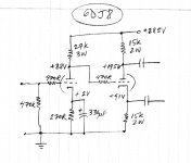
You could use the voltage amplifier to concertina (split-load or cathodyne) phase splitter topology (as in the Dyna ST35 amp). Because of the really low B+, I'd try to use 6DJ8 or 5687, because they have high transconductance (good for the concertina part) and operate well with low plate voltage. I'm pretty sure either one would have enough gain (6DJ8 has mu = 30, 5687 mu = 16)... But either one would only require one 9-pin socket per channel. How would you feel about leaving an empty socket per side?
--
Yes, the Mullard-style circuit will have too much gain unless you use it to make a lot of NFB, in which case that could be the way to go.
A cool circuit would be the dual-differential style, with two 12AU7's or 6CG7's, the first stage a LTP-phase splitter, the second stage a push-pull driver. But again, that would make a lot of gain, which you'd want to use for NFB.
The all-in-one 12AT7 LTP-phase splitter-driver with a pentode as current source would be trick. The problem is the low 300V B+ you have available. The 12AT7 would normally need a higher B+ to work with to get a decent amount of output swing (i.e. enough for 6dB of NFB).
You could use the voltage amplifier to concertina (split-load or cathodyne) phase splitter topology (as in the Dyna ST35 amp). Because of the really low B+, I'd try to use 6DJ8 or 5687, because they have high transconductance (good for the concertina part) and operate well with low plate voltage. I'm pretty sure either one would have enough gain (6DJ8 has mu = 30, 5687 mu = 16)... But either one would only require one 9-pin socket per channel. How would you feel about leaving an empty socket per side?
--
Oh,
A
Regarding .6v input sensitivity. Look at the Mac 240 schematic. They use a voltage divider (I know, not pure!) to allow for a .5 and 1.2v input.
Blair
Sure, you could do that. That's basically adding a fixed-level "volume control" after your actual volume control.
--
I tell you what Rongon,
I'm going to build out the Mullard topology and see what happens. From your perspective, is the schematic I proposed useable?
I will do it initially with the 12AU7 parallel plate VA into the 6CG7 PI, and if the sound is not what I want, I can roll it out for another pair of 6CG7s.
I really like the PI with a tube CCS you mentioned and that may be in the front end of my new amps I will build after this. PPP EL34🙂 I started working on it, but I need to get a few small $$ makers our of the way first.
I will order the Russian 6L6 tubes tomorrow, and get this project going without driving you guys crazy. I think this will be a stunning little amp when finished. The issue is that my speakers will not work at all with it. Poor little 15W amp!
Blair
- Home
- Amplifiers
- Tubes / Valves
- Bogen RP40A transformers....what to build with them?