Hi Bob,
True, but then we can consider you an expert in the same way that Doug Self is an expert. I am not surprised that you can put together an amplifier that performs that well. But this isn't the question.
<snip>
These are all good points; so much lies in the physical implementation. Even so-called experts get caught up in these kinds of problems, often leading to a lot of head-scratching. This can be true both for the implementation of the amplifier itself and for the measurement of the amplifier - even when using modern equipment like an AP that usually makes such measurements straightforward. Little of this is actually a reflection on SPICE, but rather a reflection on the difficulty of achieving the full potential of a circuit or a measurement in the real world. Before I build an amplifier, I SPICE the cr@p out of it, really getting to know it. That usually ends up in a smoother build and quicker troubleshooting (if any is needed). The simulations set up expectations for performance and behavior; those expectations should be viewed with caution, but certainly with much more than a grain of salt.
Cheers,
Bob
Any non-linearity anywhere in the amplifier will cause the input currents to be non-linear, because the NFB loop forces the amplifier output to be linear.
I see what you mean if you design a so called "Blameless" amplifier 🙄,
but there are other ways to design an amplifier that has a much better IPS and "the so called" VAS that are much less prone to the non-linear C's.🙂
Anyway the input Miller C will of course make some distortion, but it is possible to "design" out most of it.
Cheers
Reodor
But that's exactly what I did. I let the base current flow through a resistance and measured the distortion.
But, I repeat, I did, on p146 of APAD 6th edition. It is clearly pointed out that the job of the NFB loop is achieve linearity at the amplifier output, and to do this it may employ all sorts of non-linearities inside the amplifier. Look at the horrible distorted waveform on the VAS output compared with the output stage output.
Doug, none of what you have said here or on page 146 addresses the core question. We all know that the signals within the open loop amplifier must be nonlinear to make the output linear, given even just the significant nonlinearity of the output stage. To the extent that there is input signal current needed to create that nonlinear forward signal, yes, there will be some nonlinear input signal current. This will be true even if all of the forward path is perfect except the output stage. But this does not address whether that fundamental amount of required non-linear input current is the component that will account for your observations. For example, non-linear input capacitance could be a culprit whose contribution far exceeds the fundamentally-required amount of non-linear signal input current to make the output linear in spite of the output stage nonlinearity.
The core question has two parts. If your observations are truly due to nonlinear input current flowing in the source resistance, what is the physical phenomena that is the source of that nonlinear current; what is the dominant source. SPICE should handily and properly take care of the contribution you are referring to on page 146, i.e., that the signal within the forward path must be nonlinear to make the output linear. Other possibilities are things like non-linear input capacitance or non-linear input transistor beta; but do the numbers or simulations adequately point to those or similar contributors?
The second part of the core question is whether the increased source resistance made the input node more susceptible to pick-up of some kind of non-linearity, such as a nonlinear signal somehow capacitively coupled to that node. Or is it even possible that the higher source resistance somehow altered the behavior of the circuit, such as allowing an instability to occur, or to add some dc offset that exacerbated a source of non-linearity. These are just a few of many possibilities that have probably not been ruled out.
Once again, we ALL know that nonlinear Ccb, for example, will cause a nonlinear input current to flow. BUT, is that phenomena significant enough to account for your observations? SPICE seems to think not.
You did not answer what was perhaps my most important question. Did you simulate this circuit, and if so, did you see this phenomenon?
Cheers,
Bob
Usually, high performance product can not make only one prototype. Because we are human. Sometime we make a mistake. If you can achieve it only in one prototype, I think, you lucky.
Doug, none of what you have said here or on page 146 addresses the core question. <snip>
It seems to me this could be investigated with a 'real world' IPS with the rest of an amp composed of ideally VCCS and VCVS models. That way there is no internal NFB-required non-linearity because there is no nonlinearity in the VAS and OPS.
Jan
I suppose if one broke the global NFB and observe the current at base of the VAS while keeping output level the same, (reduce input level).Doug, none of what you have said here or on page 146 addresses the core question. <snip>
I have done similar for Cartesian Feedback loop RF linear amplifier, the input to the RF PA looks distorted under close loop but fine in open loop and the output vice versa. I like to think of it as the input having same amplitude of distortion of output but out of phase such that when the pre-distorted input gets distorted they cancel out and appear linear.
Just my 2 cents
It seems to me this could be investigated with a 'real world' IPS with the rest of an amp composed of ideally VCCS and VCVS models. That way there is no internal NFB-required non-linearity because there is no nonlinearity in the VAS and OPS.
Jan
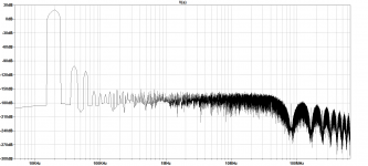
Some thing like this, the FFT shows about -80 (at Ib(Q3)) for the 3rd and no amount of gain in E1 is going to change that.
Attachments
Doug, none of what you have said here or on page 146 addresses the core question.
I beg to differ. You seem to be making awfully heavy weather of this.
We all know that the signals within the open loop amplifier must be nonlinear to make the output linear, given even just the significant nonlinearity of the output stage. To the extent that there is input signal current needed to create that nonlinear forward signal, yes, there will be some nonlinear input signal current. This will be true even if all of the forward path is perfect except the output stage.
That would seem to cover it.
But this does not address whether that fundamental amount of required non-linear input current is the component that will account for your observations. For example, non-linear input capacitance could be a culprit whose contribution far exceeds the fundamentally-required amount of non-linear signal input current to make the output linear in spite of the output stage nonlinearity.
If the amplifier is a black box, all we see is the non-linear current taken when we apply a linear input signal. The many internal amplifier mechanisms that cause it are going to be a complicated mixture and I can't see that trying to tease them out separately is a good way to spend our time.
The core question has two parts. If your observations are truly due to nonlinear input current flowing in the source resistance,
I wasn't aware there was any doubt about that.
Once again, we ALL know that nonlinear Ccb, for example, will cause a nonlinear input current to flow. BUT, is that phenomena significant enough to account for your observations? SPICE seems to think not.
I'm not sure why you are focusing on non-linear Cbc. It has a profound effect on VAS linearity, where the output voltage is large. I doubt very much if it plays any significant part in input stage distortion because the collector voltages are low, in the mV area.
You did not answer what was perhaps my most important question. Did you simulate this circuit, and if so, did you see this phenomenon?
Why is this an important question? The answer is I don't recall, but probably not because I showed practically the effect depends on transistor beta and Early voltage behaviour. Neither are well-modelled by SPICE so I see no hope of getting a useful quantitative answer.
As I'm sure you will agree, SPICE is sometimes a handy tool but measurements are the reality.
Some thing like this, the FFT shows about -80 (at Ib(Q3)) for the 3rd and no amount of gain in E1 is going to change that.
Frans what about a largish input series R, a few k? Does that make a difference?
Jan
Hi Doug,
-Chris
That pretty much says it all. I see arguments over a simulated circuit all the time. It's similar to a digital meter when people believe that each digit is significant. That's how technology can lie to you.As I'm sure you will agree, SPICE is sometimes a handy tool but measurements are the reality.
-Chris
Frans what about a largish input series R, a few k? Does that make a difference?
Jan
Not much, only at the extreme end of the scale (100kOhm or higher) the THD steps from -75 to -50 (at the output) the noise raises with the resistor value. The input-current-distortion is in line with the output behavior.
This is to be expected, the input current is less than 2uA at 2Vpp (about 500kOhm Rin).
The response of the circuit can be improved by about 20dB by introducing an ideal current mirror.
Influence of unbalanced impedances
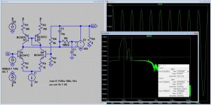
To conclude the experiment from post #8337 (page 834), I have repeated the same with two-pole compensation. In this case, distortion caused by the input stage is much smaller.
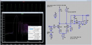
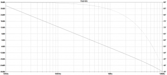
The schematic is in file schem.png, for single-pole compensation I just omitted C2 and R10. The loop gains are plotted in loop.png and loop-tpc.png.
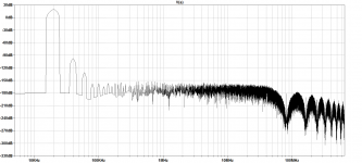
As in post #8337 with single-pole compensation, the distortion reduces with unbalanced impedances at inverting and non-inverting inputs. The balanced version is the one in the schematic, for the unbalanced one I have reduced R6 and R9 to 100R and 1K, respectively. The files bal.png and unbal.png show the spectra for balanced and unbalanced impedances.
Result: Lower impedance at the non-inverting input leads to lower distortion.
When using two-pole compensation, the spectra of balanced and unbalanced versions are tpc-bal.png and tpc-unbal.png.
Result: Here, balanced impedances yield better performance.
As indicated in post #8337, the interplay of different mechanisms can lead to different results, depending on the baseline of distortion performance.
Matthias
PS. This is only simulation, and I do now want to touch the discussion about simulation versus reality. But as reality is more complex, there should be no surprise that one can easily get quite different results.
PPS. Of course, this simulation experiment does not touch the question, whether other (stronger) non-linearities in the complete amp can lead to non-linear input currents which may reverse the result again for two-pole compensation. Maybe, this is the reason that Damir got other results in post #8320 (page 832).
In contrast, the results in the current simulation experiment fit to the ones I get for my complete amp with two-pole characteristics around input stage.
To conclude the experiment from post #8337 (page 834), I have repeated the same with two-pole compensation. In this case, distortion caused by the input stage is much smaller.
The schematic is in file schem.png, for single-pole compensation I just omitted C2 and R10. The loop gains are plotted in loop.png and loop-tpc.png.
As in post #8337 with single-pole compensation, the distortion reduces with unbalanced impedances at inverting and non-inverting inputs. The balanced version is the one in the schematic, for the unbalanced one I have reduced R6 and R9 to 100R and 1K, respectively. The files bal.png and unbal.png show the spectra for balanced and unbalanced impedances.
Result: Lower impedance at the non-inverting input leads to lower distortion.
When using two-pole compensation, the spectra of balanced and unbalanced versions are tpc-bal.png and tpc-unbal.png.
Result: Here, balanced impedances yield better performance.
As indicated in post #8337, the interplay of different mechanisms can lead to different results, depending on the baseline of distortion performance.
Matthias
PS. This is only simulation, and I do now want to touch the discussion about simulation versus reality. But as reality is more complex, there should be no surprise that one can easily get quite different results.
PPS. Of course, this simulation experiment does not touch the question, whether other (stronger) non-linearities in the complete amp can lead to non-linear input currents which may reverse the result again for two-pole compensation. Maybe, this is the reason that Damir got other results in post #8320 (page 832).
In contrast, the results in the current simulation experiment fit to the ones I get for my complete amp with two-pole characteristics around input stage.
Attachments


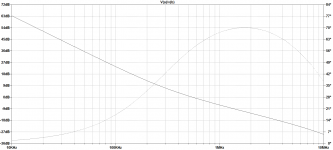

This is the one with ideal- current mirror and shown with stepper R-in
Clear. Thanks Frans.
jan
[...]
If the amplifier is a black box, all we see is the non-linear current taken when we apply a linear input signal. The many internal amplifier mechanisms that cause it are going to be a complicated mixture and I can't see that trying to tease them out separately is a good way to spend our time.
[...]
Hi Douglas,
Without teasing them out it's hard to remove the last traces of distortion.
(that's what I have learned from your books and articles 😉 )
Cheers,
E.
This is the one with ideal- current mirror and shown with stepper R-in
Hi Frans
What happens if you keep the input R in at 10k and step the C's that the input R "sees",
I think that the most important C to look at is the "input" Miller C.
Run the simulation by stepping the C's at only Q3, not both the LTP transistors.
Cheers
Reodor
Hi Douglas,
Without teasing them out it's hard to remove the last traces of distortion.
(that's what I have learned from your books and articles 😉 )
Cheers,
E.
Hello Edmond
Not the same thing at all, I suggest. You are talking about the basic amplifier distortion, where yes, sorting out all the major distortion mechanisms was essential. I suspect there at least two more so far uncategorised.
On the other hand, to completely suppress input current distortion all you have to do is drive the amplifier with a low impedance, say less than 50 Ohms. This is a good idea anyway to minimise noise.
I'm not saying it wouldn't be interesting to dig deeper than the investigation in Audio Power Amplifier Design 6th-edition goes, but it hardly seems a priority.
Hi Frans
What happens if you keep the input R in at 10k and step the C's that the input R "sees",
I think that the most important C to look at is the "input" Miller C.
Run the simulation by stepping the C's at only Q3, not both the LTP transistors.
Cheers
Reodor
I'm not going to do that (now) 🙂 but I will tell you that it will introduce more distortion. In principal equality of the two transistors will remove distortion, so, the base current distortion at the one side being the same as the distortion at the other side (including other transistor parameters) will cancel each other. But inequalities can not be canceled (duhhh...) and thus must create some thing, any thing created by the amplifier we call distortion.
The total equality of the transistors is thus an weakness of the simulation, and thus the figures (in this case [the LTP]) are overly optimistic (e.g. to good to be true). Reality must thus be worst.
On the other hand, to completely suppress input current distortion all you have to do is drive the amplifier with a low impedance, say less than 50 Ohms. This is a good idea anyway to minimise noise.
While this is a good idea, and it will remove the influence of the input-serial-resistance (source resistance) it will not change the input-current-distortion (e.g. the input current of the simulated circuit is about 2uA and it will not change by changing the generator impedance).
Last edited:
The potential gain from further analysis is to discover you can eliminate the input buffer by making a simpler change to the amplifier, therefore reducing cost in several ways.
As an author you are not obliged to exhaustively tackle every possible tool in the designer's arsenal. That would be impossible. This is why we have such a thing as philosophy. If you know the philosophy of low distortion design then you don't need to have everything explained to you, you can figure out the details as you go along.
In so far as a book provides facts to the reader it is an empirical work, and in so much as it explains how discover facts for yourself it is philosophical. In principal, the empirical shortcomings of a book should be made up for in the philosophy which in it's ideal form will allow the reader to re-create the knowledge in the book as well as whatever further knowledge he needs.
It is my observation that most books on audio design are strong on empirical knowledge, but weak on philosophy. The result is that the inevitable empirical blind spots are hard for even very conscientious readers to fill in.
- Home
- Amplifiers
- Solid State
- Bob Cordell's Power amplifier book