If the CE is also connected to AC ground, I guess I didn't understand why that was specifically pointed out as the difference.
I don't think it was called out as a difference in that respect.
"It is also called a common collector stage because the collector is connected to an AC ground".
The 'also' refers to the other naming of this circuit. I don't have the book right here, but I would guess the first name was 'emitter follower'.
As in: 'an emitter follower is also called a common collector stage because....'.
Isn't semantics wonderful!

Jan
I don't think it was called out as a difference in that respect.
The 'also' refers to the other naming of this circuit. I don't have the book right here, but I would guess the first name was 'emitter follower'.
As in: 'an emitter follower is also called a common collector stage because....'.
Isn't semantics wonderful!
Jan
 What I believe I was missing was that "common emitter" means that the input(base) is referenced to the same ground as the emitter, and like wise for the input(base) to collector of a CC. Is that a fair description?
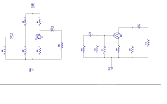
Before the advent of operation amplifier and when transistors were very expensive the circuit on the left below is how a typical small signal audio amplifier used to look. R1 and R2 are for DC biasing. The circuit on the right is the AC equivalent of the circuit on the left. It is this form that is used when comes time to calculate for example the total load resistance at the input among other things related to AC analysis.
Attachments
Yes the word 'common' means input has the same reference as the 'common' terminal.
Ground is often referred to as 'ac common' or 'signal common'.
Jan
Yes the word 'common' means input has the same reference as the 'common' terminal.
Ground is often referred to as 'ac common' or 'signal common'.
Jan
Thanks Jan! It's funny how the simplest idea can cause so much grief when misunderstood.
I find most of my audio related misunderstandings turn out to be a small error in thought or previous terminology that means something different.
When in doubt, the best tactic usually is to take the literal English meaning of a word, because when the term was coined, that was were it came from.
Jan
Jan
I read 'common emitter' as 'the input and output circuits have the emitter in common'. Since for a 4 terminal network there must be one terminal which is 'in common' between in and out due to a transistor having only 3 terminals.
Save
I read 'common emitter' as 'the input and output circuits have the emitter in common'. Since for a 4 terminal network there must be one terminal which is 'in common' between in and out due to a transistor having only 3 terminals.
🙂 good explanation.
Another source of confusion for me is that I have a bad habit of alternating between conventional and electron flow.
I need to get into the habit of using conventional flow thinking consistently, as this seems to be the more commonly used description in Solid state Literature. At least until I have a sound understanding.
When you get down to the atomic level and the physicists discuss electron flow, then they use "real" electron flow current.
Leave that to the Physicists and those that manufacture our semiconductors.
For the rest of us, we can safely stick with "conventional current" flow and it's direction.
And for AC it flows both ways, so we tend to refer to current source and load and know that current flows from the Source to the load and then MUST return to the Source. And that applies to the two way version of AC current as well as to DC current.
This Flow from and Return to the Source is fundamental to how we design our layouts.
Many here forget this and get it quite wrong. They think "ground" and that leads to many layout errors.
Last edited:
They think "ground" and that leads to many layout errors.
I was one of "them" until recently. I can see that I've picked up a few bad habits doing line Maintenance of aircraft, and didn't always pay attention to the original grounding design layout when performing a "temporary repair" in the field. It is only after reading here at DIYA and in recent books that I realize how important the layout of grounds are!
You may have missed the comparison between a layout error (according to you) and a correct layout (as you seem to prone) :They think "ground" and that leads to many layout errors.
http://www.diyaudio.com/forums/anal...nal-grounds-chassis-vs-pcb-5.html#post4764949 (posts #89, #90, #91, #92)
In post #94 of the same thread, a very common error is pointed, which may somewhat contradict what you think of "ground" :
http://www.diyaudio.com/forums/anal...nal-grounds-chassis-vs-pcb-5.html#post4964837
I did read his recent posts and contributed way back to that Thread.You may have missed the comparison between a layout error (according to you) and a correct layout (as you seem to prone) :
http://www.diyaudio.com/forums/anal...nal-grounds-chassis-vs-pcb-5.html#post4764949 (posts #89, #90, #91, #92)
In post #94 of the same thread, a very common error is pointed, which may somewhat contradict what you think of "ground" :
http://www.diyaudio.com/forums/anal...nal-grounds-chassis-vs-pcb-5.html#post4964837
I can't understand what he is testing. it was an ALL or nothing comparison. He has recently tried a different in between test, but I could not follow what he actually tested.
Difficult for me to reach any conclusion based on my lack of understanding of his tests.
In post94 Herve made three arguments or questioned other replies.
Which one are you referring to?
Last edited:
It's comparative measurements between layouts using as much as possible the ground/chassis and its low impedance for the signal path (not insulated input and output sockets, PCB ground planes relying on metallic struts attached to the metallic chassis in more than one place) and more conventional layouts.I can't understand what he is testing. it was an ALL or nothing comparison. He has recently tried a different in between test, but I could not follow what he actually tested.
If you can't get a conclusion, build two identical circuits, one with the layout you think to be the good way, and the other one as described above. Measure the noise and the susceptibility to EMI of each and compare.Difficult for me to reach any conclusion based on my lack of understanding of his tests.
In post94 Herve made three arguments or questioned other replies.
Which one are you referring to?
You : That loop will impose a current around the LOOP and that current will introduce an interference voltage in the coax/twisted pair input signal return route.
Hervé : Magnetic fields don't induce currrent in the loop.
Magnetic fields induce VOLTAGE in the loops.
I saw that and refrained from making a comment.....................
You : That loop will impose a current around the LOOP and that current will introduce an interference voltage in the coax/twisted pair input signal return route.
Hervé : Magnetic fields don't induce currrent in the loop.
Magnetic fields induce VOLTAGE in the loops.
I thought I would leave that to the experts, but none have confirmed one way, or the other.
Does the changing magnetic field cause a current to flow in a conductor, or does it cause a voltage to exist between the ends of the conductor? Or is it that both exist?
I refer to Michael Faraday.I saw that and refrained from making a comment.
I thought I would leave that to the experts, but none have confirmed one way, or the other. Does the changing magnetic field cause a current to flow in a conductor, or does it cause a voltage to exist between the ends of the conductor? Or is it that both exist?
Last edited:
A changing magnetic field induces an EMFDoes the changing magnetic field cause a current to flow in a conductor, or does it cause a voltage to exist between the ends of the conductor? Or is it that both exist?
Whether you see a voltage and/or current depends on loadsa stuff .. particularly the impedances in the loop.
Last edited:
does that mean that both current and voltage exist when the conductor forms a loop?A changing magnetic field induces an EMF
Whether you see a voltage and/or current depends on loadsa stuff .. particularly the impedances in the loop.
A changing magnetic field induces an EMF
Whether you see a voltage and/or current depends on loadsa stuff .. particularly the impedances in the loop.
EMF is Volt.
does that mean that both current and voltage exist when the conductor forms a loop?
Yes. Sometimes you have current and voltage in a circuit at the same time ...
The parasitic EMF determines the parasitic current in the loop.does that mean that both current and voltage exist when the conductor forms a loop?
You need to look up & study carefully what is EMF.EMF is Volt.
EMF is usually measured in Volts but they are NOT the same thing. Please don't expect me to teach Electrical Eng. 101
What we are discussing is complicated by the fact that IF a current flows, it generates a magnetic field too.
Michael Faraday explained all this too.
- Home
- Amplifiers
- Solid State
- Bob Cordell's Power amplifier book