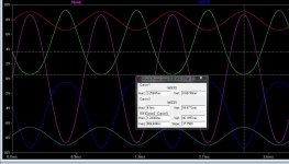
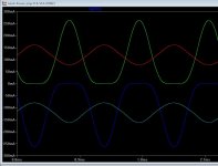
Device currents. Driver and output transistors currents 18VPP and 36vPP signal to the load. When the currents are above blow 0, they work in Class A, when signal is too large and the transistors runs out of bias they transition into class B
The other curves is the driver device currents.
The other curves is the driver device currents.
Attachments
Class A? Class B? Class AB? Class Oliver?
Time to move on.
Cheers,
Bob
I just saw Elvis leaving the building 😀
Jan
To stay a little on the subject I do feel that a lot of quality can be gained by looking at how the output devices turn-on and turn-off, here the "drivers" are connected to the output and the output is biased with a low value resistor bias spreader, this makes the output switching much softer, as the "drivers" fill in the missing current from the softer turn-on/off.
Richard Feynman said:You can know the name of a bird in all the languages of the world, but when you're finished, you'll know absolutely nothing whatever about the bird... So let's look at the bird and see what it's doing -- that's what counts. I learned very early the difference between knowing the name of something and knowing something.
That is just passing the buck on to the person who has to write the book for everyone else. We can of course understand each other pretty well but someone still has to write the book. And if we make it easier for other electronic fields to understand our work then we will get more cross-pollination.
Of course if fun is the only aim then who cares about others? I'M happy, that's all that counts, right?
Of course if fun is the only aim then who cares about others? I'M happy, that's all that counts, right?
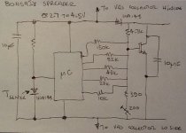
Earlier on I mentioned using a micro controller to manage the bias spreader. Attached is a concept diagram. As you can see, if you use a standard spreader to do the first order compensation, the controller is left with just the 2nd order compensation to do. With this approach you can quickly build very sophisticated compensation solutions. There is no reason why you can't use a number of sensors, or even look at the temp differentials and apply PID techniques. I have shown an adjustment pot, but this could also be eliminated. 16 pin 32 bit ARM SOIC devices go for about $2 and options with more than enough memory are readily available. The concept presented here is for a triple OPS.
You will note that the supply to the controller is not regulated, and neither is the current through the sense diodes - all the variability is taken care of in software.
A further potential benefit of course is that the whole thing could be made self calibrating.
You will note that the supply to the controller is not regulated, and neither is the current through the sense diodes - all the variability is taken care of in software.
A further potential benefit of course is that the whole thing could be made self calibrating.
Attachments
Last edited:
16 pin 32 bit ARM SOIC devices go for about $2
... plus 6 man-months of software development 😉
BTW How do you sense the actual Ibias? That's not in this concept or is it?
Jan
It appeared to me that Marantz new amps use some sort of uC etal as Bonsai is describing for bias and temp control and also a variable speed fan is controlled thru uC.
-RNM
-RNM
Is this a real problem or it's a manufactured problem? I just use more pairs of output devise. On top of safer, it definitely lower crossover distortion adding more pairs. This is documented as crossover distortion increase as load impedance is lowered. More pairs make the load impedance seen by each pair higher. eg. If you drive a 4ohm, you use 2 pairs, the equivalent load each pair see is 8 ohm. If you use 4 pairs, each pair see 16ohm!!! this is well documented in Self's book.
As I said, I can pick at least 200 sets of matching beta transistors in a day for 50 amps.
As I said, I can pick at least 200 sets of matching beta transistors in a day for 50 amps.
Last edited:
Sensing bias can be done easy as a differential signal signal taken over the emitter resistors with a JFet op amp, then all below 5 Hz can be isolated (like a servo) all's left is the bias. With this you can make an algorithm that can hold the transistors with a defined bias. A uC and a R2R DAC resistor ladder inserted in the VBE can make it possible.
Last edited:
You could add I bias sense as an additional input - but that would have to be real- time and I think very computationally heavy. In the scheme presented above, Ibias is controlled wrt to temperature to 1st order by the standard spreader and to the 2 nd order by the MCU.
The nice thing about 32 bit processors is that you can comfortably work at a high, abstract level. When I was doing my PGA2320 based preamp with LCD display, I added automatic brightness adjustment and originally used a look-up table. One of my Japanese colleagues asked me why did I do it that way? I eventually just used a formula - plenty of computing power and lots of great development tools make this type of approach very doable. So, not a weekend project, but not 6 months either.
The nice thing about 32 bit processors is that you can comfortably work at a high, abstract level. When I was doing my PGA2320 based preamp with LCD display, I added automatic brightness adjustment and originally used a look-up table. One of my Japanese colleagues asked me why did I do it that way? I eventually just used a formula - plenty of computing power and lots of great development tools make this type of approach very doable. So, not a weekend project, but not 6 months either.
The R2R ladder need not be highly accurate - a simple approx binary relationship between the resistors is ample since you are correcting for 2nd order effects. If the 1st order effect is good to within say 30 % and the second order say 20x better than this you do not need accurate tolerance parts.
I exploited this methodology 30 years ago to software calibrate instrumentation products.
I exploited this methodology 30 years ago to software calibrate instrumentation products.
no uP controlled resistors yet??? What a disappointment 😡It appeared to me that Marantz new amps use some sort of uC etal as Bonsai is describing for bias and temp control and also a variable speed fan is controlled thru uC.
-RNM
Earlier on I mentioned using a micro controller to manage the bias spreader. Attached is a concept diagram. As you can see, if you use a standard spreader to do the first order compensation, the controller is left with just the 2nd order compensation to do. With this approach you can quickly build very sophisticated compensation solutions. There is no reason why you can't use a number of sensors, or even look at the temp differentials and apply PID techniques. I have shown an adjustment pot, but this could also be eliminated. 16 pin 32 bit ARM SOIC devices go for about $2 and options with more than enough memory are readily available. The concept presented here is for a triple OPS.
You will note that the supply to the controller is not regulated, and neither is the current through the sense diodes - all the variability is taken care of in software.
A further potential benefit of course is that the whole thing could be made self calibrating.
I always cringe when someone hints that it is JUST software 🙂
Cheers,
Bob
Class B, the last word ?
Most op-amps are said to be biased in class B.
When young, I thought that class B meant 180° conduction without idle current. So I was very puzzled by the fact there was no crossover distortion.
Later, I finally understood that there is always a small idle current in the output stage and that it is the only class B viable.
Self's classification made everything clear and avoids almost any ambiguity, at least for me. Maybe sometimes, optimal class B should be clearly precised.
By the way, an interesting class B was the Blomley's amp.
Not mentionned yet in this discussion.
I always cringe when someone hints that it is JUST software 🙂
Cheers,
Bob
Yes indeed!
- Home
- Amplifiers
- Solid State
- Bob Cordell's Power amplifier book