More drivers only worsens problem of the voltage distortion between the input and output of the OPS. Even if you've eliminated that somehow, the Early effect and Cob of the drivers tends to limit how high the input impedance can be.
Not sure I completely agree. The primary manifestation of Early effect is voltage-dependent current gain. Going from a Double to a Triple reduces the sensitivity to current gain by making it much larger.
Also, in a Triple, the pre-driver can be a much smaller device, often with less Cob.
An output Quad is probably over-kill and may just introduce more problems. A Double simply does not have enough current gain and is too susceptible to beta droop.
Cheers,
Bob
I was meaning in reference to using more than an EF3. After a point it becomes more useful to start cascoding drivers because the output stage current distortions are actually swamped by the voltage distortion and the B-C leakage from Early effect.
Of course everything is fluid, nothing is black and white. There's no substitute for studying your own invention.
Of course everything is fluid, nothing is black and white. There's no substitute for studying your own invention.
I agonized for some time over whether to use a double or triple EF output stage. I was most worried about thermal compensation and stability of the triple.
In the end, I figured that given the high beta of OnSemi's new output transistors, I could just about get away with a double, if I used the beta enhanced VAS and ran it at 10mA.
It is true that the 3EF Triple has more Vbe's to worry about for bias stability, so one needs to pay a bit more attention. One approach I have used is to mount the pre-drivers and drivers together on a modest heat-sink-spreader on the amp board with their own bias spreader, then have a separate bias spreader for the output devices mounted on the main heat sink. Bear in mind that the power dissipation of the drivers is relatively constant with program.
Also keep in mind that there are other Triple topologies. For example, the Diamond Buffer Triple (DBT) has the pre-driver and driver Vbe's canceling out, especially if they are made to be at essentially the same temperature.
Yes, it is well-known that HF stability of the Triple can be more finickey than that of a Double, so better attention needs to be paid to decoupling and layout. Progressive R-C HF decoupling from the power transistor collectors back to the driver collectors, and again back to the pre-drivers can help a lot. These decoupling networks need not drop hardly any voltage to be effective. If they are made low-impedance, they also act as Zobels to damp the rails.
The output stage should never take more than 10% of the standing current of the VAS for low distortion. 5 amps output with a Double's beta squared of 1000 requires 5mA. That is way too much for a VAS with 10mA standing current. You can argue about how much beta the driver and output transistors have, but I still think the point is clear.
In my view, a Double simply does not cut it for a high-performance amplifier.
Cheers,
Bob
If a transistor is biased at 10mA and Early effect changes it's gain from 400 to 380, that's actually a 1.3uA load on the VAS because Ib changes. It behaves like a nonlinear resistor shunting the VAS output. Adding EF stages doesn't reduce this effect, and if anything increases it slightly. Just thought I'd add this in case it wasn't clear.
The NJL4281/4302 have a typical current gain of 100 at 5A, and the MJE340 driver transistor has a typical current gain of 70 at 50mA. That gives a total current gain of 7000, not 1000. For any other output transistors (and for strict worst-case design) I would be wary of using a double EF, but the new ONSemi ones have crazy current gain.
The heavier loading on the VAS is probably partly responsible for the higher HF THD in my design compared to some other Blameless type amps. I decided that I didn't really care if THD at high frequency and high power was 0.01% rather than 0.001%, but I did care about spending weeks chasing parasitics.
I didn't know about the diamond buffer triple at the time I built this, but I would certainly try it next time.
Thanks for this info, JPV.
There is something that seems amiss:
"He wrote that a resistor with a respectable Vcr of 10ppm Under 50V (typical of a feedback resistor) gives 0.05% distortion If we apply his formula for HD3 it is only 0.01%".
In my experience there seems no way that even a 100ppm metal film resistor could create 0.05% distortion, even under full output voltage conditions (say 40V rms or more) as long as the dissipation was under about 10% of rating. I don't even think a carbon film would be this bad. Could it be that the 0.05% number is off by a couple of orders of magnitude?
Bruce is extremely smart and seems never to be wrong, so maybe we are somehow mis-reading what he is saying or not getting the context right.
Assuming resistor voltage nonlinearity is not frequency-dependent, how could we then routinely get sub-0.001% THD-1 on many amplifiers where 100ppm metal film feedback resistors are used?
I wonder if BH is referring to very low-wattage SMT resistors, if it makes a difference. Is it possible that very low wattage SMT resistors are more prone to voltage nonlinearity than larger conventional discretes?
Do you have a link to the Hofer article you are referring to?
Unless I can somehow find a difference from my experience, I would say a 100ppm metal film with a very generous dissipation rating would be fine.
One approach would be to take a very good existing amplifier, measure its THD-1 in the most sensitive possible way (maybe using a twin-T notch and a spectrum analyzer, or some combination using the distortion magnifier), and then successively putting in crappier feedback resistors until the measured distortion increases.
Cheers,
Bob
There are two version with different stuff in each one but most the same.
Please Google Bruce Hofer designing for ultra low distortion et the same with ax at the end. One is a ppt presentation at AES and downloadable forom AP. The other is an article frm BH in audio express.
Great presentation with all the info required. In the AX version he explains why he prefers tracks instead of power/ground planes. As you know, we must be able to know where current is flowing to avoid coupling in critical parts.
His estimation trick of distortion in any pn junction is great stuff. The model for resistor distortion and the derivation of HD3 is impossible to check except doing the fourier transform as he cleverly did.
JPV
If a transistor is biased at 10mA and Early effect changes it's gain from 400 to 380, that's actually a 1.3uA load on the VAS because Ib changes. It behaves like a nonlinear resistor shunting the VAS output. Adding EF stages doesn't reduce this effect, and if anything increases it slightly. Just thought I'd add this in case it wasn't clear.
You are exactly right, and I think we are in agreement. Early effect of the pre-driver is there no matter what if the collector is connected to the rail.
The point I was making was in support of the need for a Triple, and that the Early effect of the driver and output transistor are greatly reduced in a Triple. It is very unlikely that you are going to have a driver transistor in a Double with a beta of over 300. Moreover, the driver is not going to be biased at only 10mA in a good design. So the use of a Triple allows us to have a much smaller consequence from the Early effect of the first transistor that the VAS sees.
It is also worth noting the current swing load on the VAS due to output current swing and compare it to the current swing inflicted on the VAS by Early effect in the pre-driver. Consider a Triple with beta-cubed equal to 1 million. Assume the p-p output current is 10A (100w @ 8ohms). We then have a VAS load variation of 10uA. This is significantly larger than the 1.3uA due to Early effect in the pre-driver.
Cheers,
Bob
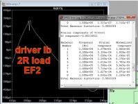
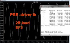
Re the EF2 vs EF3 discussion, I've settled on 100 W and below for EF2, but above this EF3. However, I do tend to run my VAS rich at typically 20 to 30'mA for the very reason that I want to keep any VAS current modulation due to output load as a small portion of the VAS standing current. I see many designs on the forum at 10 mA and below. In sims, I always look at distortion into a 2 ohms load ( yes 2 Ohms) which gives a good feel for how the amp is dealing with beta droop and VAS loading.
On an EF3 I think you can relax the VAS current a bit - but I would still run it at 15 to 20 mA.
I have had great success with EF3, and have to say the guidance in Bob's book on decoupling around the OPS, damping networks etc has worked very well - my e-Amp sounds fantastic to my ears and a lot of testing has confirmed there are no instability issues.
The NJL4281/4302 have a typical current gain of 100 at 5A, and the MJE340 driver transistor has a typical current gain of 70 at 50mA. That gives a total current gain of 7000, not 1000. For any other output transistors (and for strict worst-case design) I would be wary of using a double EF, but the new ONSemi ones have crazy current gain.
The heavier loading on the VAS is probably partly responsible for the higher HF THD in my design compared to some other Blameless type amps. I decided that I didn't really care if THD at high frequency and high power was 0.01% rather than 0.001%, but I did care about spending weeks chasing parasitics.
I didn't know about the diamond buffer triple at the time I built this, but I would certainly try it next time.
I use the ON's , too (for outputs).
I was like Carlo's- (DX) for while ... scared of the EF3.
Bob's idea of the 2 device Vbe is the ticket , both the Harmon/kardon "pricey" amps
use this (below 1) , and I do , too. NO issues.
(Below 2/3 ) is the forums "badger amp" - EF2 compared to the EF3 (with a LIN).
Now you can run all your VAS's at 4-6ma - perfect for SMD voltage stages , as well.
PS - the EF3's current gain is > 50K !
OS
Attachments
...the new ONSemi ones have crazy current..
Which ones are these?
Best wishes
David
The transistors I used were the NJL4281 and NJL4302. There is a whole line of the things in varying voltage ratings and package styles, with part numbers like NJW0201 and MJL3281. Bob Cordell calls them "Ring emitter" transistors. I believe they are all descended from Toshiba's now obsolete 2SC3281 and 2SA1302, the ones that Self referred to as "sustained beta".
Running the VAS at 30mA is certainly an alternative option. The beta enhanced VAS probably has enough gain to handle this, but the power dissipation in the VAS transistor and its current source could get a little scary.
As far as THD measurements are concerned, I'm wary of the simulated ones. And if you want to do a 20kHz THD measurement with a soundcard, you need to be sampling at 192kHz or ideally even more, to make room for the harmonics. High frequency IMD is an easier test to do with the digital gear, but I found that in my semi-pro gear, the converters and opamps had more IMD than the power amps I was trying to test, which was what motivated me to buy an analog THD analyser.
Last edited:
The transistors I used were the NJL4281 and NJL4302...
I have NJL4281/4302 too, they are excellent but I wouldn't call them "new", in fact they are about to be discontinued/obsolete, unfortunately.
Just wanted to check if there was a new release I had missed, thanks.
Best wishes
David
I rarely see this stated, but it seems obvious to me that this is desirable.I want to keep any VAS current modulation due to output load as a small portion of the VAS standing current.
I have NJL4281/4302 too, they are excellent but I wouldn't call them "new", in fact they are about to be discontinued/obsolete, unfortunately.
Just wanted to check if there was a new release I had missed, thanks.
Best wishes
David
is this a fact or a guess and by when
JPV
The NJL4281 is shown as obsolete on the ONSemi website. Recommended replacement is the NJL3281DG which shows as "Active".
So they seem to still be making Thermaltrak devices, just not that particular part with its high voltage rating.
So they seem to still be making Thermaltrak devices, just not that particular part with its high voltage rating.
Re the EF2 vs EF3 discussion, I've settled on 100 W and below for EF2, but above this EF3. However, I do tend to run my VAS rich at typically 20 to 30'mA for the very reason that I want to keep any VAS current modulation due to output load as a small portion of the VAS standing current. I see many designs on the forum at 10 mA and below. In sims, I always look at distortion into a 2 ohms load ( yes 2 Ohms) which gives a good feel for how the amp is dealing with beta droop and VAS loading.
On an EF3 I think you can relax the VAS current a bit - but I would still run it at 15 to 20 mA.
I have had great success with EF3, and have to say the guidance in Bob's book on decoupling around the OPS, damping networks etc has worked very well - my e-Amp sounds fantastic to my ears and a lot of testing has confirmed there are no instability issues.
Hi Bonsai,
These are very good points, especially regarding the VAS standing current. I only use 10mA with an output Triple, and even that might benefit from an increase. Certainly, higher VAS current is needed if using only a Double at the output. I also applaud you simming the amps into 2 ohms.
Cheers,
Bob
Thanks for this info, JPV.
There is something that seems amiss:
"He wrote that a resistor with a respectable Vcr of 10ppm Under 50V (typical of a feedback resistor) gives 0.05% distortion If we apply his formula for HD3 it is only 0.01%".
In my experience there seems no way that even a 100ppm metal film resistor could create 0.05% distortion, even under full output voltage conditions (say 40V rms or more) as long as the dissipation was under about 10% of rating. I don't even think a carbon film would be this bad. Could it be that the 0.05% number is off by a couple of orders of magnitude?
Bruce is extremely smart and seems never to be wrong, so maybe we are somehow mis-reading what he is saying or not getting the context right.
Assuming resistor voltage nonlinearity is not frequency-dependent, how could we then routinely get sub-0.001% THD-1 on many amplifiers where 100ppm metal film feedback resistors are used?
I wonder if BH is referring to very low-wattage SMT resistors, if it makes a difference. Is it possible that very low wattage SMT resistors are more prone to voltage nonlinearity than larger conventional discretes?
Do you have a link to the Hofer article you are referring to?
Unless I can somehow find a difference from my experience, I would say a 100ppm metal film with a very generous dissipation rating would be fine.
One approach would be to take a very good existing amplifier, measure its THD-1 in the most sensitive possible way (maybe using a twin-T notch and a spectrum analyzer, or some combination using the distortion magnifier), and then successively putting in crappier feedback resistors until the measured distortion increases.
Cheers,
Bob
Have you been able to download B Hofer's presentation?
His distortion of resistor is puzzeling but the paper is great.
JPV
Hi Bonsai,
These are very good points, especially regarding the VAS standing current. I only use 10mA with an output Triple, and even that might benefit from an increase. Certainly, higher VAS current is needed if using only a Double at the output. I also applaud you simming the amps into 2 ohms.
Cheers,
Bob
🙂
With about triple EF3 & double EF2.
I have a little bit experiment, EF2 have sound better than EF3, that's the result what i try on the same circuit.
I'm talking about the Sound, not Technique.
I have a little bit experiment, EF2 have sound better than EF3, that's the result what i try on the same circuit.
I'm talking about the Sound, not Technique.
matched V+/- PSSR
If I have an amp (or OpAmp IC) with the tail current CCS on the V+ side, mostly it will have a better PSSR performance than the V- side.
So, how much importance it is to have similar PSSR performance on both V+ and V- ?? Can it be made matched?
If it at least similar, wouldn't it perform better?
just curious 😀
- Home
- Amplifiers
- Solid State
- Bob Cordell's Power amplifier book