Self's data (5th edition p 81) shows small distortion increase even with 0.5% imbalance and and he comments 2nd well above 3rd even with 2%.
Have you incorrectly recalled 0.5% as 5% perhaps?
Best wishes
David
Okay, engaging my brain this time. I think it depends on the amp design too much.
The effect of LTP imbalance is inversely proportional to LTP loading. If you have heavy imbalance but little loading, you get low H2. If you have low imbalance but heavy loading, you get low H2. Both need to be significant for LTP H2 to be significant. So I would say the margin for imbalance is the % load divided by the % imbalance.
Why don't we define a "symmetry margin imbalance" for LTPs? This should be the point where H3=H2. According to sims, the point where H2=H3 occurs when load/imbalance=12.
An application would be a TMC amp Where you needed to minimize LTP distortion at audio. Let's assume we have a TMC amp with a gain of 50, 160R degeneration and a 20KHz phase shift of 2.55 degrees (not counting LP and lead comp). Assuming LTP loading is purely capacitive and converting to cartesian coordinates tells us the LTP differential must be 42mV. With a total LTP bias of 4mA:
LTP load = (42mV/Rm)/4m = .000226
LTP balance margin = load/12 = .0019%
So at over .0019% imbalance, H2 begins to raise the distortion contribution of the LTP. But this matters ONLY if the LTP has a significant contribution to total distortion. Probably not, in an advanced design. In an advanced design, the real problem is when H2 might become so large it dominates the output distortion. But this would take a gross imbalance because in advanced designs, the LTP loading is kept extremely low.
LTP balance is much more important for low or no-feedback designs. And note that if your amp is advanced, it is basically impossible to achieve the level of balance necessary to eliminate the LTP's contribution to H2. Also, it is probably swamped enormously by other THD sources.
Last edited:
Been there, done that, Self is wrong. 2nd harmonic distortions are not a good reason to e.g. match the input devices or to balance the LTP beyond the regular component tolerances.
Thanks Waly.
Cheers,
Bob
For the BJT thermal variation is 100 x 0.002/0.65 = 0.307%/°C
while for the zener it will be 100 x 0.006/10 = 0.06%/°C ,
keeping in mind that the CS current is about linearly dependent
of theses temperature variations the zener referenced CCS
stability can be improved when using a 5.6-6.3V zener.
Hi wahab,
If we are willing to lose the 5V or so of current source headroom we do when we use a zener-referenced current source instead of a feedback current source, we can use the feedback current source with a zener in series with the emitter of the feedback transistor to get about the same reference voltage for the amount across the current source emitter resistor. Also, one Vbe in series with a zener actually reduces the net amount of voltage temperature coefficient.
Cheers,
Bob
Hi, as i'm sure you're aware 😉 lots of non polar Caps made for Xovers are actually back to back electrolytics in a single case, especially high value uf.
Do you consider such Caps as distortion creators too, or just DC unbiased single electrolytics ?
Hi Zero D,
The NPs I used for my capacitor distortion evaluations in my book were true non-polar electrolytics that were sold for use in loudspeaker crossovers. You make a good point that some may not have this type of design inside, and that they might not perform as well, distortion-wise.
Cheers,
Bob
Hi wahab,
If we are willing to lose the 5V or so of current source headroom we do when we use a zener-referenced current source instead of a feedback current source, we can use the feedback current source with a zener in series with the emitter of the feedback transistor to get about the same reference voltage for the amount across the current source emitter resistor. Also, one Vbe in series with a zener actually reduces the net amount of voltage temperature coefficient.
Cheers,
Bob
I am not sure I understand you there; can you post a schematic please. Cheers.
NPs & EKVs
In Listening Tests, the KEF sounded less bright at higher levels. It had cheap NPs.
During my time in the industry, LoLoss NP caps from at least 2 of the major makers improved considerably. I won't say they were indistinguishable from polypropylenes in a treble xover but the differences were small enough that other things took precedence. One important factor was that good NPs were larger than good film caps! 😱
For bass/mid, there was no choice ... cos the values required ... and we were glad to be able to work with 2 of the best cap makers in the industry.
I have no experience of NPs in power amps but am really suspicious knowing some of the manufacturing processes involved. I'll point out that THD performance varies from maker to maker (not sure if Bateman/Self saw this) and this holds for plain electroytics too.
Oh! and the THD of even a good LoLoss NP varies with temp.
_________________
I first noted the difference between NP caps & film caps in speakers in the early 70's when I tried to replicate the original KEF 104 with my own invention using film caps while still a lad.The NPs I used for my capacitor distortion evaluations in my book were true non-polar electrolytics that were sold for use in loudspeaker crossovers. You make a good point that some may not have this type of design inside, and that they might not perform as well, distortion-wise.
In Listening Tests, the KEF sounded less bright at higher levels. It had cheap NPs.
During my time in the industry, LoLoss NP caps from at least 2 of the major makers improved considerably. I won't say they were indistinguishable from polypropylenes in a treble xover but the differences were small enough that other things took precedence. One important factor was that good NPs were larger than good film caps! 😱
For bass/mid, there was no choice ... cos the values required ... and we were glad to be able to work with 2 of the best cap makers in the industry.
I have no experience of NPs in power amps but am really suspicious knowing some of the manufacturing processes involved. I'll point out that THD performance varies from maker to maker (not sure if Bateman/Self saw this) and this holds for plain electroytics too.
Oh! and the THD of even a good LoLoss NP varies with temp.
_________________
Thanks for offering these Bob.The EKV models have not been put up on the website, but only because I didn't get to it. I had intended to put them up, but got distracted and that was awhile back (well more than a year). I'll have to go back and see what I've got. I think I did EKVs for all of those devices you listed.
Last edited:
re diff pair matching - the 2nd harmonic null for ideal or even spice transistors is very deep - but also narrow so Self's comment can make sense depending on your concept of "practical tolerance", veiws about trimming components, evaluation of real environment, operating range impact on depth of null that can be maintained
sub 1% matching runs into lots of secondary effects - differing source, feedback Z,the zoo of transistor hfe influences...
sub 1% matching runs into lots of secondary effects - differing source, feedback Z,the zoo of transistor hfe influences...
Be that as it may a variation of 0.3%/ deg. C is insignificant especially when you consider that the output impedance of the amplified negative feedback current source is at least an order of magnitude greater than that of a zener diode biased current source.
I did some sims on this subject while developing the e-Amp. Indeed, at LF the active current source is a bit better than Zener ref in terms of power supply ripple rejection, but once you get above a few kHZ, the zener ref wins hands down, and it's output impedance is flat out to 100s of KHz unlike the transistor types. I still ended up going with the two transistor variant, but on new designs may go with the zener variant . . .
I don't think changes of a few percent in the absolute value of the current source over operating temp are of concern. Sure, the VAS standing current may move about a bit as a result, but a good overall design should cope with this comfortably.
(page 27/28 in my e-Amp article)
Last edited:
re diff pair matching - the 2nd harmonic null for ideal or even spice transistors is very deep - but also narrow so Self's comment can make sense depending on your concept of "practical tolerance", veiws about trimming components, evaluation of real environment, operating range impact on depth of null that can be maintained
sub 1% matching runs into lots of secondary effects - differing source, feedback Z,the zoo of transistor hfe influences...
If enough DC feedback is applied (global or with a servo), there's no deep 2nd harmonic null. Easy to verify.
Interesting - an you show a plot or a curve? I suspect what is hapeening is the other distortion mechanisms (and associated harmonics) are being suppressed by GNF so the delta between the LTP 2nd null and everything else is smaller.
there's the classic http://users.ece.gatech.edu/~lanterma/sdiy/datasheets/transistors/AN-222.pdf
somewhere I think I've seen a suggestion for audio to trim the diff pair current balance/degen R? for minimum distortion - then inject external offset adj if needed
I try to read the classics and I have that one, but thanks for the reminder.
It prompted me to think that there are potentially two different sources of mismatch.
The transistors may differ in both hFE or in Vbe (from different IS).
So the trim for minimum distortion then adjust balance makes some sense, but probably only for a fiddly, no-NFB amp.
I wonder if Self's assertion of that high a sensitivity to LTP imbalance is right. It should be something that is easy to sim...
It was presumably intended to demonstrate the inherent non linearity of any LTP from the exponential Vbe to Ic relation so it was for an isolated LTP rather than an entire amp.
It was not simulated but measured on an Audio Precision so presumably accurate for that condition.
Okay, engaging my brain this time. I think it depends on the amp design too much.
See note above.
Best wishes
David
Interesting - an you show a plot or a curve? I suspect what is hapeening is the other distortion mechanisms (and associated harmonics) are being suppressed by GNF so the delta between the LTP 2nd null and everything else is smaller.
A present but not deep H2 null seems to imply we have two H2 sources which are 90 degrees out of phase, so they can't simply be subtracted. This makes sense since miller compensation shifts everything 90 degrees. If this is the case, then I suspect a TPC compensated amp may be capable of a greater null. Wow, one more arguing point between compensation methods.
The two sources of H2 are frequency-dependent and non-frequency dependent. As long as the H2 sources are equal in magnitude, a deep null could be had across the transition, but if imbalanced, the phase shift of the combined H2 will not match the shift of the fundamental, which is what causes the counter-H2 distortion in the LTP. So, deep null will probably never happen, especially in any amplifier without an open-loop BW exceeding the audio band. This is assuming there is any possibility of null at all considering base currents, Early effect and so on.
The use of an electrolytic cap in the feedback network is undesirable, but I showed in my book that if a non-polar electrolytic with a voltage rating of, say 100V is used, as used in loudspeaker crossovers, their distortion contribution is almost unmeasurable.
Cheers,
Bob
Hi Bob, where this in his book in which you write the voltage rating of electrolytic cap in the feedback network?
Chapter 8 - DC Servos ?
Though it is an outdated idea cap in the feedback network, is still used for basic amplifiers is an important tip.
Could associate two polarized capacitors to get a cap NP.
Interesting - an you show a plot or a curve? I suspect what is hapeening is the other distortion mechanisms (and associated harmonics) are being suppressed by GNF so the delta between the LTP 2nd null and everything else is smaller.
I should probably add: "for all practical purposes". A bipolar undegenerated LTP is obviously more sensitive to matching(s) than the degenerated case.
The idea is to keep the LTP as close as possible to the small signal condition. If the DC point is strongly modulated by the input signal, then e.g. the effect of an Early voltage mismatch also appears at the output.
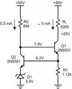
I am not sure I understand you there; can you post a schematic please. Cheers.
Hi Mike,
Here's a schematic of what I discussed. Zener diode D1 is in the emitter of the current source active feedback transistor, raising the quiescent voltage at the emitter of the current source transistor to the Zener voltage of 5.6V plus 1 Vbe. This increases the needed size of the current source emitter resistor and may increase the output impedance of this current source further still, due to larger effective emitter degeneration. Bypassing the Zener is probably desirable. This approach might decrease current source noise due to the increased emitter degeneration, but I'm not sure and have not simulated it.
Cheers,
Bob
Attachments
Current sources
I " guess" JFET CS's are outa vogue these days ?
How about OpAmp current sources https://en.wikipedia.org/wiki/Current_source
I " guess" JFET CS's are outa vogue these days ?
How about OpAmp current sources https://en.wikipedia.org/wiki/Current_source
Here's a schematic of what I discussed
You hope 0.5mA through a 5.6V zener will give you 5.6V and a regulation anywhere close to decent? Maybe in simulations, otherwise I don't think so.
A 5.6V zener has a knee current Izk~1mA and Izt=40...50mA (where the dynamic impedances are minimum and guaranteed).
Be that as it may a variation of 0.3%/ deg. C is insignificant especially when you consider that the output impedance of the amplified negative feedback current source is at least an order of magnitude greater than that of a zener diode biased current source.
Agree that for an amp whose internal temp may vary
by no more than 20°C above ambient it doesnt matter
much.
I " guess" JFET CS's are outa vogue these days ?
How about OpAmp current sources https://en.wikipedia.org/wiki/Current_source
Hi Zero D,
The problem with JFET current sources is their dependence on the very wide variation in threshold voltages of the JFET.
BTW, another thing worth mentioning about current sources involves active 2-terminal and 3-terminal IC current sources. Many of these have a significant limit on the allowable voltage rate-of-change across them. So they are OK for DC, but may often not be OK for AC signals. I suppose that if you took one of these and cascoded it with a BJT it might be OK for a VAS pull-down current source, but I have not thought very much about this.
Bottom line, be cautious before using an IC current source.
Cheers,
Bob
Bateman, in his "Capacitor Sound" series, claims you can get bi/non polar electros with full oxide thickness grown on both foils - and that they measure better on distortion
"back-to-back" construction would have one pair of foils with only the spontaneous oxide layer which is thin so that it sees large V/m - leading to greater measured distortion
even adding a polarizing V to the midpoint doesn't reduce the thin layer's contribution to distortion to the same level as full thickness oxide grown on all foils
http://www.cde.com/catalogs/AEappGUIDE.pdf suggests forming is an external operation - before slitting, winding
In section 13.8 of my book I discuss capacitor distortion and that is where I mentioned the improved performance of the NP crossover electrolytic. The 100uF, 100V NP electrolytic is fully 25 dB lower in distortion than a 100uF, 16V polarized electrolytic. The comparison of the distortions of these capacitors as a function of frequency is shown in Figure 13.3.
These capacitors were compared by flowing a 4mA rms signal current through them and measuring the THD of the voltage developed across the capacitor.
I believe that the higher voltage rating of the NP also contributes to its lower distortion.
Cheers,
Bob
- Home
- Amplifiers
- Solid State
- Bob Cordell's Power amplifier book