Hi Bob - how do you typically terminate these? Are you using connectors designed for coaxial?
Inside the amplifier, the short RG-174 runs (if needed) are just soldered point-to-point. For test leads, I just solder the RG-174 to BNC connectors. There are also occasions when I will put an RCA plug on one or both ends.
Cheers,
Bob
Dear Bob, I've been watching your videos on Burning Amp 2019, great job! and great info! thanks for sharing the knowledge! and also great book, its much thicker than the first edition, all around the best audio amp design book out there...
Dear Bob, I've been watching your videos on Burning Amp 2019, great job! and great info! thanks for sharing the knowledge! and also great book, its much thicker than the first edition, all around the best audio amp design book out there...
Thank you for your kind words!
Cheers,
Bob
...., Why?
Variation of collector voltage leaks-back to the base and is not so much absorbed by the high-impedance base divider resistors.
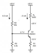
Replace that divider with a 2.7V car battery(!), the external base pin will not be influenced by collector voltage. Change 95K+5.4K to 9.5K+540r, leak-back is much less. A lower useful limit is the 10-100 Ohms between external base pin and the internal base junction. For "constant" current we often use a few diodes at a few mA to get some dozens-Ohm impedance rather than 5k. Of course if this is a current multiplying mirror then that's different. (You might cite a page number so folks don't have to flip all the pages. Even Bob may not remember a specific figure after months of production.)
This is on page 39. Thank you for answer, but Early effect means that there is a variation of collector current when collector voltage increase, so the value of beta increase. There is a base width modulation. In my mind, base current stays the same, isn't it?
Hi Jerome, BJT basics 101.
When you have a BJT biased at a fixed IC, when you change VCE you will get an associated change in VBE and in IB. If VCE increases, VBE will also decrease and IB will also decrease.
Now, going back to original question. What does "output impedance will be increased if smaller values for R2 and R3 are used" mean?
Well if the collector voltage of Q1 goes up, with smaller values of R2 and R3 the IC of Q1 increases less, less Delta IC.
So, if the collector voltage of Q1 goes up, its VCE goes up and hence the IB decreases, which is the same as a delta IB being injected into the junction of R2 and R3. This current injection, raises the base voltage of Q1, which leads to an increase in IC. This voltage increase = Delta IB x (R2||R3) and Rout = Delta V at Q1's collector / Delta IC.
Now you can see that if R2||R3 is smaller, the raise in Q1's base voltage should be smaller due to a Delta IB (caused by a delta VCE) which in turn leads to a smaller Delta IC and hence a higher Rout.
BTW, if you are starting in amplifier design, check out my video channel, it is a good companion to Bob's book (see below).
Best, Sandro
Last edited:
> base current stays the same
As I think sandrohv says: if the collector current stays "the same", and we read Early as a 'beta' change, then base current "must" change, right?
Or ask The Idiot. SPICE can give utterly wrong answers to 8 places, but the core models do good at all the main trends inside a BJT at reasonable biases.
I set up your base resistor values, and 1/10th values, and swept the collector voltage. This plots the collector dynamic impedance. I held a phone-bill to the screen to estimate the slant of the curves, to get values for collector impedance.
I am mildly surprised that 10:1 change of base impedance is only 3:1 change of collector impedance but it is too muggy here now to think.
Attachments

Hi Jerome, BJT basics 101.
When you have a BJT biased at a fixed IC, when you change VCE you will get an associated change in VBE and in IB. If VCE increases, VBE will also decrease and IB will also decrease.
Now, going back to original question. What does "output impedance will be increased if smaller values for R2 and R3 are used" mean?
Well if the collector voltage of Q1 goes up, with smaller values of R2 and R3 the IC of Q1 increases less, less Delta IC.
So, if the collector voltage of Q1 goes up, its VCE goes up and hence the IB decreases, which is the same as a delta IB being injected into the junction of R2 and R3. This current injection, raises the base voltage of Q1, which leads to an increase in IC. This voltage increase = Delta IB x (R2||R3) and Rout = Delta V at Q1's collector / Delta IC.
Now you can see that if R2||R3 is smaller, the raise in Q1's base voltage should be smaller due to a Delta IB (caused by a delta VCE) which in turn leads to a smaller Delta IC and hence a higher Rout.
BTW, if you are starting in amplifier design, check out my video channel, it is a good companion to Bob's book (see below).
Best, Sandro
These are all good and correct answers. I apologize for not having made this more clear in the book.
Cheers,
Bob
OK, so I challenged myself, for good old times...
IF RS = R2||R3, the closed form solution is
R_OUT = (r_pi+Rs)||R1 + ro*(RS+r_pi+(1+Beta)*R1)/(RS+r_pi+R1)
The first term is small compared to second so ignore. 1+Beta = Beta. Therefore,
R_OUT = ro*(RS+r_pi+Beta*R1)/(RS+r_pi+R1)
Finally, since Beta = Gm*r_pi,
R_OUT = ro*(RS+r_pi*(1+Gm*R1))/(RS+r_pi+R1)
Now you can see it from this,
If RS is huge, then R_OUT = ~ ro since the fraction approaches 1.
If RS is 0, then R_OUT = ~ro*(r_pi/(r_pi + R1) + Gm*(r_pi||R1))... which is >> ro
So, as you reduce RS = R2||R3, R_OUT increases.
Enjoy!
Last edited:
These are all good and correct answers. I apologize for not having made this more clear in the book.
Cheers,
Bob
Hi Bob, not sure if you have seen my little video channel hobby project. If you have not, take a peek (it is in my signature), I take feedback... just don't criticize the audio in the first 2 videos... I already got enough flak for that.
Best, Sandro
...apologize for not having made this more clear in the book.
It's explained. At page 39, and back at page 30.
Don't apologize. The book is already near 800 pages and $80-$180. IMHO this is the kind of basic theory well-taught in some 1970s texts. You can grab these for $5-$15, and IMHO should be digested before venturing into "audio amplifier" territory.
I am mildly shocked that my Idiot's "about 280k" was anticipated by Cordell's "about 290k", despite my different (and inappropriate) transistor. (It may only mean that mass-compiled models don't differ all that much from some default.)
Attachments
Last edited:
What is IMHO? Where this formula comes fom : R_OUT = (r_pi+Rs)||R1 + ro*(RS+r_pi+(1+Beta)*R1)/(RS+r_pi+R1)?
I made study in electronics, and I'm electronics designer, I know that analog parts is not thorough. This is the reason why, I've read Art of electronics and Microelectronics circuits ( Sedra and Smith), but the way Sandrhov explained me Early Effect is quite new for me. So if you have paper (or book) to advise me, don't hesitate. But I must read Cordell's book, I made my audio amplifier but Ireally need to improve it
I made study in electronics, and I'm electronics designer, I know that analog parts is not thorough. This is the reason why, I've read Art of electronics and Microelectronics circuits ( Sedra and Smith), but the way Sandrhov explained me Early Effect is quite new for me. So if you have paper (or book) to advise me, don't hesitate. But I must read Cordell's book, I made my audio amplifier but Ireally need to improve it
Dear Bob, do you have any comments on high power pro audio amps like the ones used on PA systems? is it just a matter of paralleling output transistors and raising the voltage rails? or is there something very different from the amps covered in your book?
What is IMHO? Where this formula comes fom : R_OUT = (r_pi+Rs)||R1 + ro*(RS+r_pi+(1+Beta)*R1)/(RS+r_pi+R1)?
Small signal analysis. Rout is the impedance looking into the collector of Q1.
IMHO = In my humble opinion.
I made study in electronics, and I'm electronics designer, I know that analog parts is not thorough. This is the reason why, I've read Art of electronics and Microelectronics circuits ( Sedra and Smith), but the way Sandrhov explained me Early Effect is quite new for me. So if you have paper (or book) to advise me, don't hesitate. But I must read Cordell's book, I made my audio amplifier but Ireally need to improve it
Sadly, you won't find it in any book. That way of thinking comes after years of circuit design experience. That is why I started my little video project, as a way to share what I learned in over a decade at Analog Devices. Interestingly, I'll be covering BJT's shortly.
Dear Bob, do you have any comments on high power pro audio amps like the ones used on PA systems? is it just a matter of paralleling output transistors and raising the voltage rails? or is there something very different from the amps covered in your book?
Nowadays, most of the high-power pro amplifiers are class D. This makes them smaller, lighter and less heat-generating. These are all important considerations when cramming many of them into a rack.
In prior years, these amplifiers were of the linear type, typically class AB, G or H. As explained in my book, there is some semantic ambiguity between class G and class H. In any case, the class G amplifiers with 2 or 3 different rail voltages and many output transistors were the workhorses for many years. The legendary Crest 8001 was a very good example of these amplifiers. It was quite a heavy amplifier 🙂.
Cheers,
Bob
Coming back do the circuit in page 39, it is better to have R3 as forward diodes or a zener, such the new effective RS = R2||incremental resistance of diodes is low and you get higher Rout.
Might as well use a 6.3WVDC electrolytic capacitor to drop the impedance at the current source base even lower, at audio frequencies. If low is good then lower is better.
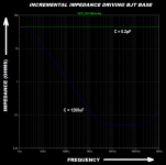
This 1200uF cap is only 13 mm tall and 3.5mm diameter. Its Equivalent Series Resistance is 0.049 ohms and DigiKey sells it for 41 cents (19 cents if you buy 100 of them).
LTSPICE simulation below: green trace is "no capacitance" (0.2pF in LTSPICE); blue trace is 1200uF. Impedance is lower (better) across the entire audio band. Not bad for $0.41.
By the way, you get this benefit whether the base bias scheme is a pair of resistors, a resistor and two diodes as shown here, or a resistor and a Zener diode.
_
Attachments

Last edited:
Coming back do the circuit in page 39, it is better to have R3 as forward diodes or a zener, such the new effective RS = R2||incremental resistance of diodes is low and you get higher Rout.
That is correct. That circuit is only one of many ways to implement a current source, and was just illustrated as a way to teach the concepts.
Cheers,
Bob
- Home
- Amplifiers
- Solid State
- Bob Cordell's Power amplifier book