Yes, the Devil is in the details, and at this point we are delving deeply into the details. This is where simulation with accurate models can help a lot.
The reduction of local Miller feedback loop gain by introduction of the emitter resistor, in my opinion, is largely offset by the introduction of local feedback in another way, namely by degeneration.
The substantial reduction of Early effect distortion by the emitter degeneration should also be considered, but one might argue that the larger local Miller feedback loop gain in the undegenerated case might also have an equal benefit.
Speaking of Early effect and the output impedance of the VAS, I think that at lower frequencies where the Early-effect-dominated open-loop output impedance becomes less than the impedance of the Miller compensation capacitor, the effectiveness of the shunt feedback of the Miller feedback becomes relatively less. For example, with a 30 pF Miller capacitor, the impedance of that capacitor at 5 kHz is 1 Meg, higher than you are likely to get with an undegenerated VAS transistor with Early effect.
The trade of more emitter degeneration for less Miller shunt feedback may increase the net output impedance of the compensated VAS, making the VAS a bit more susceptible to distortion by the nonlinear loading of the output stage, especially in the case of just a 2 EF output stage, but this is a bit speculative on my part.
Cheers,
Bob
Why not reduce the Early effect by a factor of 100 by simply cascoding the VAS transistor? It's simple, cheap, and, according to the histograms in 1st edition of Bob's book, it also contributes a measure of distortion reduction.
Cascoding the VAS gives you the opportunity to analyze the effect(s) of VAS emitter degeneration alone, without worrying about Early effect interactions.
Cascoding the VAS gives you the opportunity to analyze the effect(s) of VAS emitter degeneration alone, without worrying about Early effect interactions.
This is true, and a good point. Cascoding the VAS does increase complexity, reduce headroom and slightly reduce phase margin in the local Miller feedback loop, however (signal passing through 3 transistors instead of two).
The use of a 2T VAS, in combination with emitter degeneration, does a quite remarkable job of suppressing the Early effect, and I rarely bother to cascode the VAS (although I did so in my MOSFET power amplifier with error correction and it did make an improvement). Using good VAS transistors with a high beta*VA figure of merit is also very important.
Cheers,
Bob
This is only half right. Assuming an conventional Miller-compensated VAS, no the global O/L gain will not be substantially effected, but the local loop gain of the VAS (as enclosed by the "Miller" compensation capacitor) will be very much effected. The emitter degeneration resistor aids VAS stability, after all by, lowering the local loop gain. And this does indeed have real potential to impact upon the amplifiers linearity primarily by reducing the amount of local negative feedback available for linearising the VAS.
The paper by Cherry that I referenced is an analysis of the sensitivity of the common power amplifier topology (long-tailed pair IPS, VAS,emitter follower OPS with overall negative feedback) to variations in various component parameters. My "in a nutshell" comments pertained to that paper and the subsequent related articles in EW+WW.
That JAES paper by Cherry is still, I believe, quite useful as it provides insight by means of mathematical analysis (lots of algebra) as contrast with numerical analysis (SPICE). These modes of analysis complement one another.
Cherry was a strong advocate for CE OPS. I do wonder if he was on to something but because of the inertia around usage of follower OPS ("conventional wisdom") his recommendation was not more widely adopted. In more recent times the Nelson Pass F5 design is an example of how far 4 transistors can go.
@ Poldaudio: But doesn't the Vas emitter resistor on itself improve linearity, offsetting the loss of loop gain? I wouldn't know which effect is greater. What do you think?
Jan
Jan
Pre Ordered a copy of the 2nd Edition.
Thanks a lot Bob for all the time you have put in to bringing this book to us all.
Thanks a lot Bob for all the time you have put in to bringing this book to us all.
Last edited:
Pre Ordered a copy of the 2nd Edition.
Thanks a lot Bob for all the time you have put in to bringing this book to us all.
Thanks!!
Cheers,
Bob
Hi David,
You are correct, although I have never used a capacitor across the VAS emitter resistor for that purpose. I have instead, at times, put a small resistor in series with the Miller compensation capacitor to introduce a zero (and in theory eliminate a high-frequency right-half-plane zero that can be caused by feedforward through the Miller capacitor.
Cheers,
Bob
What is the criteria to select that resistor?, in other words, how can one find/calculate the right half plane zero which needs to be cancelled? or is it mostly a trial an error process?
Why not reduce the Early effect by a factor of 100 by simply cascoding the VAS transistor? It's simple, cheap, and, according to the histograms in 1st edition of Bob's book, it also contributes a measure of distortion reduction.
Cascoding the VAS gives you the opportunity to analyze the effect(s) of VAS emitter degeneration alone, without worrying about Early effect interactions.
Speaking of Self's book again, he doesnt seem to favor the cascoded VAS+Emmiter follower like Bob does, Self either cascodes or uses Darlington VAS, not both. Also Bob seems to really like MOSFETs whilst Self likes BJT, both authors make compelling arguments to support their ideas.
Sorry for the comparisons Bob! I love both books and cant wait for the 2nd ed.
What is the criteria to select that resistor?, in other words, how can one find/calculate the right half plane zero which needs to be cancelled? or is it mostly a trial an error process?
The resistor should be at least equal to 1/gm, where gm is the net transconductance of the VAS (including any reduction in transconductance due to emitter degeneration). As the value of the resistor is increased beyond this point, a real zero will be introduced into the transfer function.
That real zero introduced can be used to cancel a pole at a higher frequency well above ULGF to gain some additional phase margin. Just don't over do it with this technique, as it can begin to eat into gain margin. Bear in mind also that those higher-frequency parasitic poles can be somewhat unpredictable in frequency and can also move around with transistor operating points.
Cheers,
Bob
Speaking of Self's book again, he doesnt seem to favor the cascoded VAS+Emmiter follower like Bob does, Self either cascodes or uses Darlington VAS, not both. Also Bob seems to really like MOSFETs whilst Self likes BJT, both authors make compelling arguments to support their ideas.
Sorry for the comparisons Bob! I love both books and cant wait for the 2nd ed.
Glad you like both books. Looking at things from more than one angle can always be helpful. Similarly, the same thing being explained in different ways can also be helpful.
Doug and I are not that far apart with respect to the VAS. As I mentioned above, I usually go for the 2 EF VAS without cascode. When I used the Darlington-cascode VAS in my MOSFET amplifier with error correction, I was going all-out for performance, especially at 20 kHz, and I also used boosted rails for the IPS/VAS, so the headroom loss from the cascode did not hurt.
I'm pretty much of an equal-opportunity guy when it comes to BJT vs MOSFET outputs. Without error correction it is difficult, even with vertical MOSFETs, to get measured distortion numbers as good as BJTs, at least with sinewaves under the usual static lab conditions, but non-EC MOSFET amplifiers that can do, say, 0.02% THD at 20 kHz can seem to perform better in the crossover region because they are not so picky about bias setting and dynamic temperature swings, and also because you can run them hotter without getting into gm doubling. With BJT outputs, I will always do some kind of triple, and will never do a CFP output. On the other hand, there are those who would argue that the CFP mitigates some of the dynamic temperature swing issues (but the price paid for that in other ways is too high for me). It really is a pick your poison world 🙂.
To this day, if someone held a gun to my head and told me to make the best possible amplifier that could do less than 0.001% THD at any power level, I would do it with vertical MOSFETs and error correction (and I would probably add a dose of TMC compensation). That amplifier would cost a bit more than a BJT of the same power rating, would dissipate somewhat more than a similar BJT, and it would require boosted rails to make best use of the main rail voltages. But all of that is just my preference, and the approach that would give me the most confidence in meeting the objective.
I think Doug and I also differ on preference for input stages, where I lean more toward using JFETs and he seems not to like them as much. The truth is that a fine amplifier can be made with either technology when it is engineered well and there is great attention to detail in execution.
Cheers,
Bob
Of course it does to some extent but I think most miss the extent to which emitter degeneration reduces the Miller loop gain.@ Poldaudio: But doesn't the Vas emitter resistor on itself improve linearity, offsetting the loss of loop gain? I wouldn't know which effect is greater. What do you think?
Jan
A VAS transistor running at an Iq of 20mA will have a little re of a little over 1 ohm. Add a 120 ohm emitter degeneration resistor and you've reduced that common emitter amplifier's open loop transconductance by almost two orders or magnitude.
Simulate a typical Thompson Topology (NOT Lin!) "Blamless" amp with and without VAS emitter degeneration and put the loop gain probe in series with the Miller compensation capacitor. In the non-degenerated case you might be freaked out by just how high the unity loop gain frequency is (>100MHz is easily achieved) and how close the phase margin is to the edge.
Another thing to keep in mind is that ability of the VAS to deliver a low output impedance over the full audio frequency range so as to combat the non-linear input impedance of the power output stage is probably more important than the intrinsic (unloaded) linearity of the VAS itself.
As an aside, for an published example of the importance of high Miller loop gain, have a critical read of Samuel Groner's "A new audio amplifier topology with push-pull VAS". Although he doesn't seem to be aware of it, the linearity improvement afforded by his symmetrical VAS, over the non-symmetrical one, is largely if not mostly due to the higher open loop transconductance of the former. As such his paper doesn't present an apples-apples comparison.
To this day, if someone held a gun to my head and told me to make the best possible amplifier that could do less than 0.001% THD at any power level, I would do it with vertical MOSFETs and error correction (and I would probably add a dose of TMC compensation). That amplifier would cost a bit more than a BJT of the same power rating, would dissipate somewhat more than a similar BJT, and it would require boosted rails to make best use of the main rail voltages. But all of that is just my preference, and the approach that would give me the most confidence in meeting the objective.
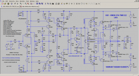
In my experience, is quite difficult to stabilize EC and two-pole compensation (TPC,TMC,TMIC)
One example is my last CFA VMOS amp which uses TMIC and EC (at least it's stable in simulation)
Attachments
Of course it does to some extent but I think most miss the extent to which emitter degeneration reduces the Miller loop gain.
A VAS transistor running at an Iq of 20mA will have a little re of a little over 1 ohm. Add a 120 ohm emitter degeneration resistor and you've reduced that common emitter amplifier's open loop transconductance by almost two orders or magnitude.
Simulate a typical Thompson Topology (NOT Lin!) "Blamless" amp with and without VAS emitter degeneration and put the loop gain probe in series with the Miller compensation capacitor. In the non-degenerated case you might be freaked out by just how high the unity loop gain frequency is (>100MHz is easily achieved) and how close the phase margin is to the edge.
Another thing to keep in mind is that ability of the VAS to deliver a low output impedance over the full audio frequency range so as to combat the non-linear input impedance of the power output stage is probably more important than the intrinsic (unloaded) linearity of the VAS itself.
As an aside, for an published example of the importance of high Miller loop gain, have a critical read of Samuel Groner's "A new audio amplifier topology with push-pull VAS". Although he doesn't seem to be aware of it, the linearity improvement afforded by his symmetrical VAS, over the non-symmetrical one, is largely if not mostly due to the higher open loop transconductance of the former. As such his paper doesn't present an apples-apples comparison.
I have to disagree with some of your points. First, in terms of numbers, I typically run my VAS at 10 mA, so re' is about 2.6 ohms. I usually degenerate by a factor of about 10 with a 22 ohm emitter resistor. So this is relatively less degeneration that you are describing. For a 20 mA VAS, this would correspond to a degeneration resistor of only about 10 ohms.
With the Miller compensation shunt feedback, the output impedance of the VAS at high frequencies will theoretically be on the order of 25 ohms or so when the VAS is run at 10 mA and degenerated 10:1. This is pretty low. In practice, the VAS output impedance will be a bit higher due to the attenuation of the Miller capacitor against the input capacitance of the first VAS transistor. Simulation will confirm this.
The issues being discussed here also underline the great advantage of using an output triple instead of a mere output double. If you are concerned about VAS output impedance not being low enough, it seems you should also be concerned about the input impedance of the output stage not being high enough.
The use of a push-pull VAS improves things in many ways, but is of limited relevance to the matter here of whether the VAS should be degenerated or not. The push pull VAS brings added performance to the table by largely suppressing 2H created in the VAS and by doubling the amount of signal current the VAS can deliver for a given amount of VAS bias current. The helps the VAS better drive the Miller compensation capacitor and the output stage.
Cheers,
Bob
Can you elaborate on why you dont use CFP in the output stage? stability ?
The problems with the CFP output stage are described in Section 5.4 of my book. They are further discussed in the added Output stages II chapter in my second edition due out in May.
Study also the implementation of the CFP output stage in Self's book and note the fact that there is a limited amount of turn-off current for the output transistor and that he has to starve the output stage of bias current to avoid gm doubling, resulting in a very small class A operating region, among other things. The Oliver condition does not usually apply to CFP output stages, and its benefit of optimization of crossover distortion in them can only be poorly approximated. Take a look at the spikey distortion residual in Figures 12.4 and 12.5 of Self's 6th Edition (these are CFP outputs mislabeled as EF outputs).
In fairness to Bryston, they do a better job with the CFP portion of their hybrid CFP-EF output stage. I discuss that in my second edition as well.
Yes, stability can be a concern as well.
Cheers,
Bob
In my experience, is quite difficult to stabilize EC and two-pole compensation (TPC,TMC,TMIC)
One example is my last CFA VMOS amp which uses TMIC and EC (at least it's stable in simulation)
EC and TMC do require a bit more sophistication in design, but are both perfectly stable when properly implemented.
Cheers,
Bob
https://www.eetimes.com/document.asp?doc_id=1280059&page_number=2have a critical read of Samuel Groner's "A new audio amplifier topology with push-pull VAS
That is one good article.
The issues being discussed here also underline the great advantage of using an output triple instead of a mere output double. If you are concerned about VAS output impedance not being low enough, it seems you should also be concerned about the input impedance of the output stage not being high enough.
Hmm , notice that most solid state builds over the last 2 years are EF3's
now. advice taken !!
OS
Bob, you might enjoy taking another look at Winfield Hill's 10 MHz, 1000 V/usec, 100W_8R power amplifier. If his name rings a bell, that's because he's one of the two authors of a famous book called "The Art Of Electronics" ... and he's the one who did the fantastic work on ultra low noise BJTs that you can actually buy today (hint: better than the obsolete former champion, 2SB737), see table 8.1 of the 3rd edition.
His amplifier is here on diyAudio:
You may find his amp's boosted supply rails to be thought provoking. He uses small, PCB mounted, isolated DC-to-DC converter modules which generate XX VDC output, and connects them in series with the amplifier's main rails. They're isolated, you can connect their output however you wish. Voila, boosted rails for the IPS and VAS. Without buying an extra transformer, without sourcing a weirdo custom transformer having numerous secondaries, without winding your own extra coils on a vendor-bought toroid (Cordell 1st ed, p.348)
Since the IPS + VAS current requirements are modest, you have the option to use DC-to-DC modules with 12 VDC output, and still remain comfortably within the output current and output power capabilities of low cost modules. Twelve volts allows the freedom to HEAVILY filter the SMPS output, incurring plenty of IR voltage drop across the filters if you wish, and still get a very smooth rail that's boosted more than enough to do the job.
It's a pretty cute idea, and the cost of the modules is surprisingly modest. Check out the Murata ones on DigiKey. Winfield happened to choose DC-DC modules from Micro Power Direct, but that company doesn't distribute through Digikey or Mouser or Element14, so we do not speak of them here at diyAudio 🙂
- Home
- Amplifiers
- Solid State
- Bob Cordell's Power amplifier book