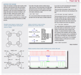
BTW, I ran across some other obscure LTspice commands: .state, .rule and .output.
See attached. Can probably be used to advantage also in analog circuits.
Jan
Hi Jan,
It's too small for me to read.
🙂😱 I mean got bass with music..... or close to it.
🙂 test signal haha lol 🙂
😎
Last edited:
BTW, I ran across some other obscure LTspice commands: .state, .rule and .output.
See attached. Can probably be used to advantage also in analog circuits.
Jan
..... arbitrary waveform generator ?
🙂
-RM
great links, thank you!
for me Kolumni's book was inspirating
but the links you showed... they lead to treasures!
thank you very much for them!
for me Kolumni's book was inspirating
but the links you showed... they lead to treasures!
thank you very much for them!
Spice models 'Cordell-Models.txt'
Hello Bob,
first of all: Thank you sincerely for making available these Spice models!
As described with the different fitting procedures in your book, this must have been a lot of work. Especially the dynamic characteristics of power BJT are in good agreement with datasheet curves. Unfortunately, this cannot even be said from manufacturer models of more recent devices as e.g. NJW0821/3821.
During some intensive simulation exercises, I came across three issues related to your Spice models. Could you please comment on these? (According to a German phrase, there is something like a "curse of the good act" ;-)
1. You state the Early voltage for BC550/60 transistors as around VAF=160. Models from different manufacturers specify decreasing VAF values with increasing current gain group. This is consistent with all BC550 transistors having a comparable "figure of merit". So, does a BC550 from current gain group "C" (current gain above 500 at 10mA) really possess such a good Early voltage?
2. According to datasheet, the JFET LS844 has forward and reverse capacities of at most 8pF and 3pF, respectively. When using the .OP directive and looking into the Spice log file, I always read Cgs and Cgd values of less than 1pF for your LS844 model. Do you know, how pessimistic the datasheet values are?
3. Although already a bit dated, the BD139/40 transistors still fit well in many applications. Especially for these types it is known that devices from different manufacturers differ remarkably in speed. Your models lead to transition frequencies well above 100MHz at 100mA collector current. So, who manufactured the transistors you have measured?
Kind regards,
Matthias
Last edited:
Hello Bob,
first of all: Thank you sincerely for making available these Spice models!
As described with the different fitting procedures in your book, this must have been a lot of work. Especially the dynamic characteristics of power BJT are in good agreement with datasheet curves. Unfortunately, this cannot even be said from manufacturer models of more recent devices as e.g. NJW0821/3821.
During some intensive simulation exercises, I came across three issues related to your Spice models. Could you please comment on these? (According to a German phrase, there is something like a "curse of the good act" ;-)
1. You state the Early voltage for BC550/60 transistors as around VAF=160. Models from different manufacturers specify decreasing VAF values with increasing current gain group. This is consistent with all BC550 transistors having a comparable "figure of merit". So, does a BC550 from current gain group "C" (current gain above 500 at 10mA) really possess such a good Early voltage?
2. According to datasheet, the JFET LS844 has forward and reverse capacities of at most 8pF and 3pF, respectively. When using the .OP directive and looking into the Spice log file, I always read Cgs and Cgd values of less than 1pF for your LS844 model. Do you know, how pessimistic the datasheet values are?
3. Although already a bit dated, the BD139/40 transistors still fit well in many applications. Especially for these types it is known that devices from different manufacturers differ remarkably in speed. Your models lead to transition frequencies well above 100MHz at 100mA collector current. So, who manufactured the transistors you have measured?
Kind regards,
Matthias
Hi Matthias,
Thanks for your kind words. Without looking in detail at modeling materials that are quite a few years old, here are some tentative answers to your questions:
1. VAF usually goes down for devices with increased beta of a given type, tending to keep the VA * beta product in the same range (figure of merit). For model generation, I only looked at a couple of samples for each device, and they were probably all from the same gain group. I doubt that my samples had beta in the 500 range.
2. Capacitances on datasheets are often somewhat pessimistic, especially quoted maximum values. That having been said, those numbers sound low. My recommendation is to use the LSK489, which is a newer, lower-noise version of the LS844. Use the SPICE model on the Linear Systems website. It should be more accurate.
3. I don't recall who manufactured the BD139/140 transistors I used. Beta droop at high current can be difficult to model properly in SPICE. I also concentrated most of my modeling of beta droop on power output and driver devices, where it is a problem most often.
Hope this helps, and this kind of feedback is helpful to me as well.
Cheers,
Bob
Hi Bob,
thanks for the prompt reply.
For the first point:
From your remarks and manufacturer models I conclude, that the "figure of merit" for BC550/60 should not be overestimated. In many, but not all, applications, a high Early voltage won't be necessary. Another type with high "merit" value is apparently the BC337-40 or its SMD variant BC817-40. Here, the manufacturer models agree in stating high Early voltage and high current gain at the same time (VAF around 100 together with beta around 400).
For the second point:
Thank you for the hint; I mistakenly thought that LSK489 would be an improved version of LSK389 (with its high tranconductance, but also capacitances). The LSK489 Spice model from Linear Systems unfortunatley includes the same CGD=CGS=1e-12 values as your LS844 model.
I will check that and report results. Perhaps, these values have to be increased; the LSK489 datasheet now additionally contains a typical capacity.
Third point:
The collector current 100mA probably does not yet lead to remarkable Ft droop for these transistors. In the thread "Overunity transistors", Elvee provided measurement results of Ft and Cbc values for BD139/40 from different manufacturers. Your models seem to fit best to Philips or Motorola devices. Nevertheless, it is a pitty that one cannot use these ubiquitous types in (slightly advanced) applications, since manufacturers apparently made a big mess with device characteristics.
Cheers,
Matthias
Last edited:
Matze, here are several different BC5xxC models with measured VAF values from different manufacturers. I altrered them from Cordell's models.
I'm not sure which devices Cordell's measurements came from but their Rbb seems much too low to be from Phillips/NXP.
Note that after the Fairchild aquisition the OnSemi BC5xxC are most likely the Fairchild parts.
Code:
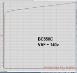
.MODEL BC550C_Cko npn IS=45e-15 BF=689 VAF=110 IKF=0.09 ISE=4600e-15 NE=2 NF=0.9965 RB=167 RC=1 RE=0.04 CJE=6.2p MJE=0.35 VJE=0.75 CJC=3.5p MJC=0.25 VJC=0.4 FC=0.5 TF=1n XTF=10 VTF=10 ITF=1 TR=10e-9 BR=12.2 IKR=0.34 EG=1.2 XTB=1.65 XTI=3 NC=0.996 NR=1.0 VAR=120 IRB=7e-5 RBM=1.1 XCJC=0.6 ISC=5e-15 Vceo=45 Icrating=100m mfg=OnSemi
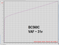
.MODEL BC560C_Cko pnp IS=60e-15 BF=900 VAF=37 IKF=0.10 ISE=70e-15 NE=1.42 NF=1 RB=170 RC=1.0 RE=0.05 CJE=6.2p MJE=0.3 VJE=0.75 CJC=3.5p MJC=0.3 VJC=0.75 FC=0.5 TF=1n XTF=7 VTF=4 ITF=0.45 TR=10e-9 BR=3 IKR=0 EG=1.1 XTB=1.5 XTI=3 NC=2 ISC=0 Vceo=45 Icrating=100m mfg=OnSemi
.model BC550C_Ckf npn IS=45e-15 BF=689 VAF=162 IKF=0.09 ISE=4600e-15 NE=2 NF=0.9965 RB=167 RC=1 RE=0.04 CJE=18.7e-12 MJE=0.35 VJE=0.75 CJC=6.2e-12 MJC=0.25 VJC=0.4 FC=0.5 TF=595e-12 XTF=10 VTF=10 ITF=1 TR=10e-9 BR=12.2 IKR=0.34 EG=1.2 XTB=1.65 XTI=3 NC=0.996 NR=1.0 VAR=120 IRB=7e-5 RBM=1.1 XCJC=0.6 ISC=5e-15 Vceo=45 Icrating=100m mfg=Fairchild
.model BC560C_Ckf pnp IS=60e-15 BF=900 VAF=160 IKF=0.10 ISE=70e-15 NE=1.42 NF=1 RB=170 RC=1.0 RE=0.05 CJE=19e-12 MJE=0.3 VJE=0.75 CJC=3.9e-12 MJC=0.3 VJC=0.75 FC=0.5 TF=600e-12 XTF=7 VTF=4 ITF=0.45 TR=10e-9 BR=3 IKR=0 EG=1.1 XTB=1.5 XTI=3 NC=2 ISC=0 Vceo=45 Icrating=100m mfg=Fairchild
.MODEL BC550C_Cp npn IS=45e-15 BF=689 VAF=162 IKF=0.09 ISE=4600e-15 NE=2 NF=0.9965 RB=167 RC=1 RE=0.04 CJE=18.7e-12 MJE=0.35 VJE=0.75 CJC=6.2e-12 MJC=0.25 VJC=0.4 FC=0.5 TF=595e-12 XTF=10 VTF=10 ITF=1 TR=10e-9 BR=12.2 IKR=0.34 EG=1.2 XTB=1.65 XTI=3 NC=0.996 NR=1.0 VAR=120 IRB=7e-5 RBM=1.1 XCJC=0.6 ISC=5e-15 Vceo=45 Icrating=100m mfg=NXPI'm not sure which devices Cordell's measurements came from but their Rbb seems much too low to be from Phillips/NXP.
Note that after the Fairchild aquisition the OnSemi BC5xxC are most likely the Fairchild parts.
Matze, here are several different BC5xxC models with measured VAF values from different manufacturers. I altrered them from Cordell's models.
I'm not sure which devices Cordell's measurements came from but their Rbb seems much too low to be from Phillips/NXP.Code:.MODEL BC550C_Cko npn IS=45e-15 BF=689 VAF=110 IKF=0.09 ISE=4600e-15 NE=2 NF=0.9965 RB=167 RC=1 RE=0.04 CJE=6.2p MJE=0.35 VJE=0.75 CJC=3.5p MJC=0.25 VJC=0.4 FC=0.5 TF=1n XTF=10 VTF=10 ITF=1 TR=10e-9 BR=12.2 IKR=0.34 EG=1.2 XTB=1.65 XTI=3 NC=0.996 NR=1.0 VAR=120 IRB=7e-5 RBM=1.1 XCJC=0.6 ISC=5e-15 Vceo=45 Icrating=100m mfg=OnSemi .MODEL BC560C_Cko pnp IS=60e-15 BF=900 VAF=37 IKF=0.10 ISE=70e-15 NE=1.42 NF=1 RB=170 RC=1.0 RE=0.05 CJE=6.2p MJE=0.3 VJE=0.75 CJC=3.5p MJC=0.3 VJC=0.75 FC=0.5 TF=1n XTF=7 VTF=4 ITF=0.45 TR=10e-9 BR=3 IKR=0 EG=1.1 XTB=1.5 XTI=3 NC=2 ISC=0 Vceo=45 Icrating=100m mfg=OnSemi .model BC550C_Ckf npn IS=45e-15 BF=689 VAF=162 IKF=0.09 ISE=4600e-15 NE=2 NF=0.9965 RB=167 RC=1 RE=0.04 CJE=18.7e-12 MJE=0.35 VJE=0.75 CJC=6.2e-12 MJC=0.25 VJC=0.4 FC=0.5 TF=595e-12 XTF=10 VTF=10 ITF=1 TR=10e-9 BR=12.2 IKR=0.34 EG=1.2 XTB=1.65 XTI=3 NC=0.996 NR=1.0 VAR=120 IRB=7e-5 RBM=1.1 XCJC=0.6 ISC=5e-15 Vceo=45 Icrating=100m mfg=Fairchild .model BC560C_Ckf pnp IS=60e-15 BF=900 VAF=160 IKF=0.10 ISE=70e-15 NE=1.42 NF=1 RB=170 RC=1.0 RE=0.05 CJE=19e-12 MJE=0.3 VJE=0.75 CJC=3.9e-12 MJC=0.3 VJC=0.75 FC=0.5 TF=600e-12 XTF=7 VTF=4 ITF=0.45 TR=10e-9 BR=3 IKR=0 EG=1.1 XTB=1.5 XTI=3 NC=2 ISC=0 Vceo=45 Icrating=100m mfg=Fairchild .MODEL BC550C_Cp npn IS=45e-15 BF=689 VAF=162 IKF=0.09 ISE=4600e-15 NE=2 NF=0.9965 RB=167 RC=1 RE=0.04 CJE=18.7e-12 MJE=0.35 VJE=0.75 CJC=6.2e-12 MJC=0.25 VJC=0.4 FC=0.5 TF=595e-12 XTF=10 VTF=10 ITF=1 TR=10e-9 BR=12.2 IKR=0.34 EG=1.2 XTB=1.65 XTI=3 NC=0.996 NR=1.0 VAR=120 IRB=7e-5 RBM=1.1 XCJC=0.6 ISC=5e-15 Vceo=45 Icrating=100m mfg=NXP
Note that after the Fairchild aquisition the OnSemi BC5xxC are most likely the Fairchild parts.
Keantoken, did you measure these devices yourself? I fear that it is too optimistic to assume an Early voltage of 160V for a group "C" transistor. Hopefully, some 30V are too pessimistic.
Bob provided good power BJT models. (E.g., when recently investigating a stability problem with a 3281/1302 output stage during recovery from clipping, I found that only his models properly include changing Cbc values according to datasheet.)
Many of us also use his small-signal models, and the BC550/60 combo can be seen quite often. So it would be nice if these models were as dependable as the large-signal ones.
Maybe, building on Bob's work, we can make an effort. Is there anybody who can perform such a measurement? If I remember right, this is not exactly easy due to heating problems with these small devices.
Matthias
Yes, I measured them, and the measurements corroborate the performance of my Kmultipliers. There are some transistors with much higher Vaf but not many and none that I know of with comparable Hfe, noise and Ft.
Unfortunately a VAF of 30 is not pessimistic. VAF is actually one of the parameters that varies the most wildly between different manufacturers in my experience.
Also the idea that VAF varies inversely with Hfe doesn't seem to be very reliable. As far as I've seen it's a VERY loose relationship. I'd like to see someone test BC550A, 550B, 550C etc all from the same manufacturer to compare Hfe vs VAF. But if you're comparing different transistors or different manufacturers, it's all over the place.
Last edited:

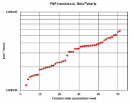
Thank you for sharing these and the results from previous post!A couple of scatter plots:
_
The results are in line with keantokens remark that the "figure of merit" is not that well behaved. Nevertheless, for pnp devices (are these BC560?), one finds VAF less than 100 for gain group "C".
Do you also have such a scatter plot for the npn devices? The Fairchild model BC549/50, e.g., states an Early voltage of 160V, but the current gain is clearly more in the "B" category. Other models I checked (LTSpice, Nexperia) even only state less than VAF=100 for group "B" devices.
Matthias
Hi Bob,2. Capacitances on datasheets are often somewhat pessimistic, especially quoted maximum values. That having been said, those numbers sound low. My recommendation is to use the LSK489, which is a newer, lower-noise version of the LS844. Use the SPICE model on the Linear Systems website. It should be more accurate.
the LSK489 datasheet is remarkably detailed, lots of curves also for typical capacity behaviour.
I'd like to make an effort and try to incorporate these into the model. For small-signal JFET are not that important in a "typical" power amp, you did not describe fitting procedures for dynamic characteristics as detailed as for BJT in your book.
But do you have a reference in mind that could be used as good starting point when diving into this subject?
Cheers,
Matthias
Fascinating that there are no 100-150VAF PNP transistors sampled in the 300Hfe range. I wonder what that chart would have looked like back when thousands of 2Nxxxx transistors were available. Perhaps the chart is split due to a split between transistors characterized for high power and low power use, excluding those in-between.
The transistors with the highest FOM do seem to follow the inverse relationship more closely.
Also I wonder how many of those VAF values were contaminated with the quasi-saturation region.
The transistors with the highest FOM do seem to follow the inverse relationship more closely.
Also I wonder how many of those VAF values were contaminated with the quasi-saturation region.
Last edited:
Also I wonder how many of those VAF values were contaminated with the quasi-saturation region.
Since it was me defining the experiment, me performing the measurements, and me recording the data, I happen to know the answer: none.
I intentionally measured ro = dVce/dIce at a high collector voltage (Vce=6V and Vce=16V), so high as to guarantee there was no quasi-saturation. And I took pictures of every transistor under test, so I could go back and look at them some day in the distant future, if I ever felt like it.
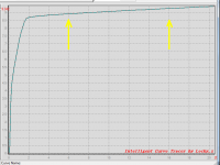
Just now I looked at the pictures again, and plucked out the absolute worst-of-them-all PNP transistor, the one whose quasi-saturation range is widest. Figure below. In the region (0.3V < Vce < 1.9V), it's quasi-saturated. At 6V and 16V, it's not.
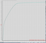
edit- I just discovered a sub-folder called ZoomIns, which contained the attached image #2. It's the same transistor, measured a month later (when I knew which transistors were best and which were worst), at a higher magnification. You can see quasi-saturation better.
_
Attachments
Last edited:
- Home
- Amplifiers
- Solid State
- Bob Cordell's Power amplifier book