In my opinion, that's a matter of opinion; different people will give different answers, and all answers will be equally correct.How much Phase Margin does does a current source need. Is it not enough just to get them stable?
In my opinion, you want enough Phase Margin so that an ill-designed and sloppy implementation by the least experienced reader of Bob Cordell's 2nd edition, is nevertheless comfortably stable.
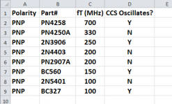
In my opinion that means it has a comfortable margin of safety even with the worst possible choice of device types (PN4258 @ fT=700MHz ?), and with the worst possible low impedance load on the current source output (5 ohms ?), and with the worst possible amount of stray capacitance on the sensitive feedback nodes (200 pF ?), and with the worst possible choice of current ratio between output transistor and control transistor (3:1 ?)
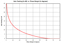
So, how much safety is "a comfortable margin of safety" in my opinion? Well, when I plot the equations in this web page I get the graph shown below. The standard advice given to undergraduate control theory students is "don't quit until you've got at least 45 degrees of phase margin" which corresponds to about 3 dB of gain peaking on that graph. But since I'm talking about phase margin in the worst of the worst case possible scenarios, I'm willing to tolerate, oh let's just say, 9 dB of gain peaking. From the graph, that's 20 degrees of phase margin. In my opinion.
Attachments
Hi David,
And your entire post was what I was getting at. These audio buzz words drive me nuts.
-Chris
And your entire post was what I was getting at. These audio buzz words drive me nuts.
-Chris
My mentor in IC design used to say "If it works on first silicon, you weren't aggressive enough." God almighty that was a fun place to work.
But he said that in the days before wafer steppers and $100K mask sets {which now cost north of $5M for nosebleed digital}
Where did you work at that time? I was in linear IC design at Bell Labs from 1972 through 1982. I remember what a PIA it was working with lateral PNPs. When BTL developed the junction-isolated complementary process (originally for IC needs created by the Picturephone project) us linear IC designers were ecstatic and never looked back. Our op amps had diamond buffer output stages by circa 1980. Those op amps were also TPC compensated for extra in-band loop gain for our Biquad active filters (we referred to it as "T" compensation).
We used to have a joking saying: "It worked in MY lab". Those were the days.
Cheers,
Bob
Bob,
Is there a pc board or jfet kit in the works for the Hafler dh220C presentation from burning amp?
Is there a pc board or jfet kit in the works for the Hafler dh220C presentation from burning amp?
In my opinion, that's a matter of opinion; different people will give different answers, and all answers will be equally correct.
In my opinion, you want enough Phase Margin so that an ill-designed and sloppy implementation by the least experienced reader of Bob Cordell's 2nd edition, is nevertheless comfortably stable.
In my opinion that means it has a comfortable margin of safety even with the worst possible choice of device types (PN4258 @ fT=700MHz ?), and with the worst possible low impedance load on the current source output (5 ohms ?), and with the worst possible amount of stray capacitance on the sensitive feedback nodes (200 pF ?), and with the worst possible choice of current ratio between output transistor and control transistor (3:1 ?)
So, how much safety is "a comfortable margin of safety" in my opinion? Well, when I plot the equations in this web page I get the graph shown below. The standard advice given to undergraduate control theory students is "don't quit until you've got at least 45 degrees of phase margin" which corresponds to about 3 dB of gain peaking on that graph. But since I'm talking about phase margin in the worst of the worst case possible scenarios, I'm willing to tolerate, oh let's just say, 9 dB of gain peaking. From the graph, that's 20 degrees of phase margin. In my opinion.
I agree.
The only caveat I would add is that if the designer is willing to simulate in his particular arrangement, with his particular worst case specs of his transistors, etc., etc., he may be able to ease somewhat the definition of worst worst case that was given above.
Short of doing a formal loop gain analysis of the current source, either by itself or in-situ in the actual application, it can provide quite useful insight to do transient and/or ac simulation by injecting a pulse or ac signal current stimulus into one of the current source nodes and see if the waveform at the injection point shows a lot of ringing or if the ac response at the injection point shows a lot of peaking. Doing these sorts of tests can also be a decent sanity check on the loop gain analysis.
Cheers,
Bob
Those op amps were also TPC compensated for extra in-band loop gain for our Biquad active filters (we referred to it as "T" compensation).
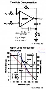
NSC talked about Two Pole Compensation on the datasheet of their LM101, which dates back to 1967, image below. (click on the X in the lower left corner to magnify it to Full Size). Citation: Robert J. Widlar, "A New Monolithic Operational Amplifier Design", NSC technical paper TP-2, June, 1967.
My aggressive mentor and I worked here
_
Attachments
Bob,
Is there a pc board or jfet kit in the works for the Hafler dh220C presentation from burning amp?
No current plans, but I'm pretty sure that Linear Systems could be convinced to make a JFET kit available for it.
Cheers,
Bob
NSC talked about Two Pole Compensation on the datasheet of their LM101, which dates back to 1967, image below. (click on the X in the lower left corner to magnify it to Full Size). Citation: Robert J. Widlar, "A New Monolithic Operational Amplifier Design", NSC technical paper TP-2, June, 1967.
My aggressive mentor and I worked here
_
Yes, TPC has been used for quite a long time, probably before IC op amps. That is a good reference you provided. We were certainly not the first to use it, but I am not aware of anyone else who integrated it into the IC op amp prior BTL.
Cheers,
Bob
Which signal transistors are closest/best compliment match as might be seen on a characteristic curve tracer? Needing minimum selection. Is there a new modern list which could be created for DIY?
THx-RNMarsh
THx-RNMarsh
ticknpop,
once the schematic shows up here, i'm sure there will be a few boards coming out shortly afterwards.
hopefully, at least one that Bob can bless ...
🙂
btw, bob, did you give any thought to adding the xl-280's trimmer cap for "tuning"?
mlloyd1
once the schematic shows up here, i'm sure there will be a few boards coming out shortly afterwards.
hopefully, at least one that Bob can bless ...
🙂
btw, bob, did you give any thought to adding the xl-280's trimmer cap for "tuning"?
mlloyd1
Bob,
Is there a pc board or jfet kit in the works for the Hafler dh220C presentation from burning amp?
Which signal transistors are closest/best compliment match as might be seen on a characteristic curve tracer? Needing minimum selection.
You would need to find someone who has access to a large number of NPN/PNP complementary pairs of transistors, AND who has access to a curve tracer. Then you would need to provide her with an incentive, a motivation, to take a whole bunch of data for you. Depending upon her age and financial condition, this might be as little as a few pizzas and a couple cases of beer. Or if you're really lucky you might find someone who would accept this arrangement: "I'll supply the transistors, you take the data, and when you're all done, you get to KEEP the transistors."
Personally, I suspect that "the answer" may include surface mount discrete transistors, just because all new semiconductor developments today are deployed in SMD. So you might very well need to supply your datataking employee with test sockets for surface mount devices, perhaps like the one shown below.
Attachments
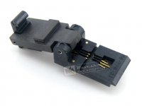
That is a perfect project for a 3D plastic printer......................So you might very well need to supply your datataking employee with test sockets for surface mount devices, perhaps like the one shown below.
Any volunteer to do the software to generate those two shapes?
Who could print these cheaply?
http://www.waveshare.com/product/sockets-adapters/test-burn-in-sockets/tsop-msop-sot/499-p44-00.htm
Last edited:
You would need to find someone who has access to a large number of NPN/PNP complementary pairs of transistors, AND who has access to a curve tracer. .
You mean one has to buy every small signal transistor known to mankind to find out? Maybe we could start with just the list of compliments from various mfr ? Then from that list start testing pairs to find those which really are very good compl.
Does such a list exist somewhere? Or begin with suggestions?
[i have a curve tracer]
THx-RNMarsh
I've been looking at Toshiba's 2SC3324 and 2SA1312. They look good on the data sheets. Low noise and 120V too. But there are no models for these transistor.
Not only should someone test transistors but also make up models for them as well.
So I guess we must up the anti.
Not only should someone test transistors but also make up models for them as well.
So I guess we must up the anti.
Hi Richard,
Start with the transistor manuals. Manufacturers often note which parts are intended to be complementary to each other. Then there are compliments that engineers and service people might know about.
Sadly, my knowledge is limited to discontinued parts. I have to learn about an entirely new set of transistors now. And they are a pain to prototype projects with because they shouldn't be reused.
-Chris
A quick search on DigiKey found three complementary pairs where the NPN and the PNP are housed in the same physical package. They are the 3946, the 847, and the 2207. Datasheets below.
Attachments
Hi Richard,
Start with the transistor manuals. Manufacturers often note which parts are intended to be complementary to each other. Then there are compliments that engineers and service people might know about.
Sadly, my knowledge is limited to discontinued parts. I have to learn about an entirely new set of transistors now. And they are a pain to prototype projects with because they shouldn't be reused.
-Chris
Please explain why they should not be reused?
Hi David,
Mostly because there will be no new supply and getting replacements in the future will be even more difficult. Add to this the high likelihood of running into remarked parts is great. Then, on top of this, the current parts are generally less expensive.
I'm like you. I'd really be very happy using the old parts I am familiar with. I am learning that for new designs, you really ought to be using something in current production and available through authorized channels. I'll use my old ones up as I search for those devices that will become industry standard parts with excellent performance.
-Chris
Hi David,
Mostly because there will be no new supply and getting replacements in the future will be even more difficult. Add to this the high likelihood of running into remarked parts is great. Then, on top of this, the current parts are generally less expensive.
I'm like you. I'd really be very happy using the old parts I am familiar with. I am learning that for new designs, you really ought to be using something in current production and available through authorized channels. I'll use my old ones up as I search for those devices that will become industry standard parts with excellent performance.
-Chris
Mostly they are not new parts. They are repackaged in SMT with new part numbers.
It's bit tricky finding the old parts but once the number system has been figured out you just take a guess and find them. I found all sorts of transistors I thought were obsolete and gone forever. In fact some of the old parts are available in higher power in SMT packages. The MPSA06/A56 for example are available PTZA06 1000mW in a SOT223
- Home
- Amplifiers
- Solid State
- Bob Cordell's Power amplifier book