Hi Bob,
I've only skimmed your book so far and didn't notice that you cover it also; here is a comment on your version of that design:
What's wrong with this picture? 🙂
I've only skimmed your book so far and didn't notice that you cover it also; here is a comment on your version of that design:
What's wrong with this picture? 🙂
Last edited:
Hi PB2,
Guests cannot view attachments for this link. I can't see what is being pointed to.
Can you enlighten me?
Thanks,
David.
If you have Self's book it is this:
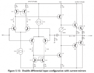
This is from the fifth edition of Self's Audio Power Amplifier Design Handbook, page 132.
Figure 5.12
It is a dual comp differential input with mirrors - which does not work. I know this to be a fact because I built it as a senior in college many years ago.
If you have Self's book it is this:
This is from the fifth edition of Self's Audio Power Amplifier Design Handbook, page 132.
Figure 5.12
It is a dual comp differential input with mirrors - which does not work. I know this to be a fact because I built it as a senior in college many years ago.
Thanks PB2,
I was looking at the wrong page.
David.
attachment
Now you can see it. 😉
Not only can guests not view attachments on the referenced 'diy-audio-engineering' site .....
Now you can see it. 😉
Attachments
Hi Bob,
I've only skimmed your book so far and didn't notice that you cover it also; here is a comment on your version of that design:
What's wrong with this picture? 🙂
Hi Pete,
First of all, I had been unaware that Self had also copied Randy's mistake. That is interesting that he overlooked that. I also note that Self did not reference Slone regarding that circuit.
The solution I came up with works fine, but everything is a matter of engineering degree and proper component value choice. My solution uses a helpered current mirror with a resistor between the collectors (a differential shunt resistor). This resistor establishes the voltage needed to define the VAS standing current while still allowing the use of the current mirror to promote balance in the LTP and allow high input stage gain if desired.
The larger this resistor, the more the VAS standing current is subject to variation due to mismatched components. If one needs to tolerate larger mismatches, then one needs to employ a smaller differential shunt resistor. If one wants to use much higher input stage tail current, as did the poster in the link, one needs to use a smaller shunt resistor).
The 47k I mention in the book actually provides a rather high gain (something like 50 or 100) and is used with a VAS where the standing current is only 1 mA. I chose the 47k value to have reasonable VAS current setting with the component variations I assumed, but certainly engineers who want to be able to use components with wider tolerances, higher standing current, etc, can choose a smaller value for the shunt resistor.
The key point is that I recognized the problem and provided an extremely simple solution that does not give up an undue amount of DC gain in the input stage. Numerous other solutions exist, but they are typically quite a bit more complicated and significantly larger amounts of input stage gain are of little use in most cases.
It is also true, however, that I should have spent more text on explaining the factors governing the choice of that resistor to ensure adequately accurate setting of the VAS standing current.
Cheers,
Bob
Hi Pete,
First of all, I had been unaware that Self had also copied Randy's mistake. That is interesting that he overlooked that. I also note that Self did not reference Slone regarding that circuit.
Bob
Why the assumption that Self has read Randy's book? I do believe that an author should be aware of as much published info as possible but I would lean more toward the AES, IEEE journals, etc. The topology is obvious if you follow the thinking that a diff amp is good, dual diff is better, mirrors are good leads to .... dual diff with mirrors. Not saying that I agree with this line of thinking; I just wanted to try it many years ago - it was not a major project of anykind, just something I was trying to do between classes and projects for credit.
Did you actually build and test your version?
Hi Pete,
I agree. I was perhaps wrongly assuming that Self read Slone. I also agree that the topology is a fairly obvious extension of other topologies as you describe. It is interesting to think that two smart guys would independtly make the same blunder. BTW, I don't know if either of them SPICE'd the circuit, but this is a case where a simple SPICE run under the right conditions could lead one to think the VAS standing current is defined in this circuit.
I did build the circuit and it worked fine (I just built the IPS/VAS and obtained the negative feedback from a simple pre-driver stage). However, we all know that verifying that something works in the lab is necessary but not sufficient. Right out of the tube my transistors were within better than a mV of each other. Similarly, the 1% MF resistors I used were well closer than within 1% of each other.
For that reason I did simulate the circuit with deliberate imbalances introduced as Vbe offsets or resistor value mismatches. My methodology was definitely not as formal as a monte carlo simulation, but I did get a feel for how sensitive the circuit was. Introducing a 2 mV offset into the Vbe of one transistor would change VAS standing current by about 1.5 mA out of 10 mA. Introducing a 1% error into an emitter resistor would cause a slightly larger change in standing current. One can definitely argue that when lots of things pile up in the wrong direction, changes in VAS standing current can become unacceptable. It is ultimately a matter of judgment and tradeoffs.
The point is, with this very simple circuit you have a way of making the standing current become defined to within the tolerance you are willing to live with using components with tolerances you are willing to obtain. I usually like to see the devices in the input stage really well matched - e.g., monolithic BJT pairs matched better than 1 mV and degeneration resistors (including in the current mirrors) matched to much better than 1% (input stages that use large amounts of emitter degeneration like to have very well-matched emitter resistors for best performance). Even 0.1% resistors are not that expensive these days - guys doing balanced input circuits use them all the time to get decent CMRR.
This circuit as shown probably has about 10X the DC voltage gain of a conventional arrangement that does not use a current mirror. If you want more stability of VAS standing current, or be able to use more poorly-matched components, you are free to use a smaller value than 47k as the differential shunt, and still be way better off than the conventional circuit.
Cheers,
Bob
Is there any book store that carries it and accepts paypal?
Regards
NEW Designing Audio Power Amplifiers - Cordell, Bob - eBay (item 150507230157 end time Nov-14-10 09:51:53 PST)
Cheaper than Amazon and FREE shipping.
I paid $28.41 shipped from Borders by being a member and using a
coupon. I was really getting annoyed with how many e-mailings they
sent, but I used the coupons and got excellent discounts on Bob's and
Floyd Toole's recent book. I just filter the mailings into a folder now,
and go there for coupons when I want to buy something.
I preordered and it came about 2 weeks ago - a bit later than most.
Last edited:
NEW Designing Audio Power Amplifiers - Cordell, Bob - eBay (item 150507230157 end time Nov-14-10 09:51:53 PST)
Cheaper than Amazon and FREE shipping.

NEW Designing Audio Power Amplifiers - Cordell, Bob - eBay (item 150507230157 end time Nov-14-10 09:51:53 PST)
Cheaper than Amazon and FREE shipping.
Published by TAB Books??? Even has the TAB logo on the cover illustration.
Hmmm....
Published by TAB Books??? Even has the TAB logo on the cover illustration.
Hmmm....
Ah, TAB's a division of McGraw-Hill...
The link says in the description ''subject: computers & internet''. Yep, I wanna build a 400W ppmTHD20 ADSL modem. LOL.🙂
Bob I have a question about figure 2.14 and 2.15.
How can you determine open-loop bandwidth as a 613Hz ?
Becaues when I start to determine the value I get a different result.
F = 1 / ( 2 * pi * 714 * (1241 * 300pF) ) = 599Hz
I'm just curious from where this difference comes.
How can you determine open-loop bandwidth as a 613Hz ?
Becaues when I start to determine the value I get a different result.
F = 1 / ( 2 * pi * 714 * (1241 * 300pF) ) = 599Hz
I'm just curious from where this difference comes.
Ah, TAB's a division of McGraw-Hill...
Hi Damon,
That cover depiction is old. McGraw-Hill originally planned to publish it under the TAB line, but later changed their mind.
Cheers,
Bob
Hi Pete,
I agree. I was perhaps wrongly assuming that Self read Slone. I also agree that the topology is a fairly obvious extension of other topologies as you describe. It is interesting to think that two smart guys would independtly make the same blunder. BTW, I don't know if either of them SPICE'd the circuit, but this is a case where a simple SPICE run under the right conditions could lead one to think the VAS standing current is defined in this circuit.
I did build the circuit and it worked fine (I just built the IPS/VAS and obtained the negative feedback from a simple pre-driver stage). However, we all know that verifying that something works in the lab is necessary but not sufficient. Right out of the tube my transistors were within better than a mV of each other. Similarly, the 1% MF resistors I used were well closer than within 1% of each other.
For that reason I did simulate the circuit with deliberate imbalances introduced as Vbe offsets or resistor value mismatches. My methodology was definitely not as formal as a monte carlo simulation, but I did get a feel for how sensitive the circuit was. Introducing a 2 mV offset into the Vbe of one transistor would change VAS standing current by about 1.5 mA out of 10 mA. Introducing a 1% error into an emitter resistor would cause a slightly larger change in standing current. One can definitely argue that when lots of things pile up in the wrong direction, changes in VAS standing current can become unacceptable. It is ultimately a matter of judgment and tradeoffs.
The point is, with this very simple circuit you have a way of making the standing current become defined to within the tolerance you are willing to live with using components with tolerances you are willing to obtain. I usually like to see the devices in the input stage really well matched - e.g., monolithic BJT pairs matched better than 1 mV and degeneration resistors (including in the current mirrors) matched to much better than 1% (input stages that use large amounts of emitter degeneration like to have very well-matched emitter resistors for best performance). Even 0.1% resistors are not that expensive these days - guys doing balanced input circuits use them all the time to get decent CMRR.
This circuit as shown probably has about 10X the DC voltage gain of a conventional arrangement that does not use a current mirror. If you want more stability of VAS standing current, or be able to use more poorly-matched components, you are free to use a smaller value than 47k as the differential shunt, and still be way better off than the conventional circuit.
Cheers,
Bob
I agree with everything you state here, and I am surprised by how well your prototype worked given Glen's analysis. I do understand your points about the transistors coming from the same lot, I have made the same point myself here on the board. Yes, I experimented with hand matched devices and .1% resistors to see how well I could balance a diff pair years ago. I doubt that .1% resistors make any sort of audible difference in most audio amp diff pair applications.
My prototype was just a line stage with no power devices to keep it simple. I held onto it since I did a soldered bread board and was able to find it among my stuff.
Last edited:
Bob I have a question about figure 2.14 and 2.15.
How can you determine open-loop bandwidth as a 613Hz ?
Becaues when I start to determine the value I get a different result.
F = 1 / ( 2 * pi * 714 * (1241 * 300pF) ) = 599Hz
I'm just curious from where this difference comes.
Hi jony,
You are right on the nose. I re-checked the way that I arrived at the open-loop bandwidth frequency and I had introduced some round-off errors. You have good eyes!
Cheers,
Bob
Hi Damon,
That cover depiction is old. McGraw-Hill originally planned to publish it under the TAB line, but later changed their mind.
Cheers,
Bob
I'd consider that an upgrade. 😀
- Home
- Amplifiers
- Solid State
- Bob Cordell's Power amplifier book