Bob, why don't you check out these EKV models by Ian Hegglun:
LACAv8 - PAK2 devo
They are part of his article in Linear Audio. I tested them and they didn't match the datasheet. But then I realized the datasheet didn't match itself, so no wonder. I don't have access to Ian's article so I will try to contact him.
The VDMOS model in LTSpice does support subthreshold conduction now that Mike updated it. It is modeled a bit differently from EKV so I don't know which is more correct. However the EKV models show far less gate current than the VDMOS models, so I'm thinking the VDMOS with subthreshold parameters may be better.
Thanks, keantoken,
I'll definitely check those out. I have not yet gotten around to reading Ian's article, but I'm quite sure he likely did a good job on the models.
Could you clarify what you mean by the datasheet did not match itself?
I do plan to cover the VDMOS with subthreshold conduction in my next edition.
Not sure what you are referring to by gate current. Are you talking about dc gate leakage current? Can you elaborate?
Cheers,
Bob
...The VDMOS model in LTSpice does support subthreshold conduction now that Mike updated it...
Excellent. where did you learn this?
I just wrote to Richard Lee that tests revealed the VDMOS model simulated distortion much more accurately that I expected. That would explain it.
Best wishes
David
It's here:
Undocumented LTspice - LTwiki-Wiki for LTspice
Only a few VDMOS models have subthreshold parameters included, else there is no subthreshold modeling unless you add the parameters yourself.
AFAIK the initial benefit of VDMOS was accurate modeling of capacitance variation with Vgs, which results in much larger distortion figures, which may explain your results.
However the VDMOS models still have the glitchy crossover spikes, which get rounded off as you increase the subthreshold slope.
However when you take equivalent models using EKV and VDMOS, the transition to subthreshold conduction is modeled differently. So only once we have accurate subthreshold curves for Lfets will we know which model is more accurate.
I have not yet gotten around to reading Ian's article, but I'm quite sure he likely did a good job on the models.
Could you clarify what you mean by the datasheet did not match itself?
Not sure what you are referring to by gate current. Are you talking about dc gate leakage current? Can you elaborate?
This post should clarify some things:
http://www.diyaudio.com/forums/solid-state/248105-slewmaster-cfa-vs-vfa-rumble.html#post4075474
I too thought that the models must have been made from direct data and optimized for accuracy, but it was not to be. I talked to Ian and he told me he had no information to go on for making the models so he basically did what seemed to be realistic. In his case after all, the output stage used a controlled switching scheme so the behavior of the output transistors wasn't really critical.
It's here:
I had seen the site but not taken in that bit, thanks
AFAIK the initial benefit of VDMOS was ... capacitance variation... which may explain your results.
Yes, I tried to explain that in another thread but it was not well received.
It made the numbers look worse.😉
However the VDMOS models still have ...spikes, which get rounded off as you increase the subthreshold slope.
Capacitance variation presumably was the dominant factor in the tests I checked.
However when you take equivalent models using EKV and VDMOS, the transition to subthreshold conduction is modeled differently. So only once we have accurate subthreshold curves for Lfets will we know which model is more accurate.
After the reception of my last comments, I think I will keep that to myself😉
Best wishes
David
After the reception of my last comments, I think I will keep that to myself😉
Best wishes
David
Please share to me 🙂
Short version:
Almost everyone uses NMOS type simulation models. Using these models the gate currents are much less than they should be.
This produces impressive distortion figures, and some would rather use the bad models than face the reality that real devices are not that good.
Cordell's VDMOS type models give accurate gate currents, so they are mostly accurate.
However, even VDMOS type models are not accurate in the crossover region.
So while VDMOS type models are a huge step up from NMOS type models, they can still be improved, although we need some measurements to do that.
In that aspect I'd love to have well modeled Exicon models. I suspected the ones I'm using aren't all that accurate. But it's the best I could find on the net.
I know someone who could get us some curves:
http://www.diyaudio.com/forums/analogue-source/154210-mpp-206.html#post4085353
http://www.diyaudio.com/forums/analogue-source/154210-mpp-206.html#post4085353
ASC of the JAES amp?
Does anyone have an ASC of Bob's HEC amplifier?
I have some results from another HEC amplifier that I would like to compare.
Best wishes
David
Does anyone have an ASC of Bob's HEC amplifier?
I have some results from another HEC amplifier that I would like to compare.
Best wishes
David
Does anyone have an ASC of Bob's HEC amplifier?
I have some results from another HEC amplifier that I would like to compare.
Best wishes
David
Hi Dave,
Unfortunately, I do not have one. I don't recall using SPICE to design it and of course I did not have LTspice. Also, I'm not so sure how the IRF132 and IRF9130 used in the amplifier would compare to verticals for which we have decent models.
RMAF was great. I love that show.
Cheers,
Bob
Slightly OT perhaps but relevant non the less......
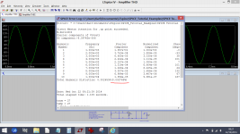
Does anyone know the reasons for the change in LTSpice following an update and the way distortion data is now shown.
This is Bob's own amp and file (from the book fig 19.7). What is the reading in brackets showing ?
Does anyone know the reasons for the change in LTSpice following an update and the way distortion data is now shown.
This is Bob's own amp and file (from the book fig 19.7). What is the reading in brackets showing ?
Attachments
I can't find any info about it in the LTSpice helpfile or changelog. You can try asking Mike directly using the email address in the help menu under "about LTSpice".
Explanation from Mike Engelhardt is here,
http://www.diyaudio.com/forums/software-tools/263590-whats-ltspice-doing-there.html#post4097547
http://www.diyaudio.com/forums/software-tools/263590-whats-ltspice-doing-there.html#post4097547
Hi
I am reading your book and I have question in page 144 Figure 7.14. I think the Q5 should have the base emitter connected instead of Q6. I just want to verify.
Thanks
I am reading your book and I have question in page 144 Figure 7.14. I think the Q5 should have the base emitter connected instead of Q6. I just want to verify.
Thanks
Hi
I am reading your book and I have question in page 144 Figure 7.14. I think the Q5 should have the base emitter connected instead of Q6. I just want to verify.
Thanks
Hi Alan,
You've got a good eye 🙂.
Cheers,
Bob
Thanks Mr Cordell, this is a very good book. I've been reading your book for a few days. I designed bipolar IC before and studied most of the circuit configurations. But I have never seen a book on SS amplifier that is so good in analysis of pros and cons of each configuration. I particularly like the analysis of distortion. I learn so much from this book. I don't know how many times I said "Oh yeh!!! I see!!!"Hi Alan,
You've got a good eye 🙂.
Cheers,
Bob
I will go to Amazon and give you a 5 star rating.
Thanks
Thanks Mr Cordell, this is a very good book. I've been reading your book for a few days. I designed bipolar IC before and studied most of the circuit configurations. But I have never seen a book on SS amplifier that is so good in analysis of pros and cons of each configuration. I particularly like the analysis of distortion. I learn so much from this book. I don't know how many times I said "Oh yeh!!! I see!!!"
I will go to Amazon and give you a 5 star rating.
Thanks
Thank you so very much for your kind words. I am happy you are enjoying the book. I designed bipolar linear ICs as well in my professional career.
Cheers,
Bob
- Home
- Amplifiers
- Solid State
- Bob Cordell's Power amplifier book