That would make sense but if VaF/Ic = Ro (output resistance) then isnt the gain ultimately limited by Ro/(Re + 1/gm).?.
Yes, for the voltage gain. I am talking about the transimpedance gain. Here, the transimpedance gain doesn't depend on the degeneration.
This is not right.
If you add degeneration to the second stage you ll increase
the first stage output level wich will increase its distorsion ,
yet the VAS better linearity wont allow to compensate
for the first stage said harsher conditions , hence ,
feedback distribution matters as its application is not
freely transferable from a stage to the other while
keeping the same global efficency.
Wahab, please make an effort and get rid of your naïve image of an audio amp as three voltage gain stages (IPS, VAS, OPS). Also, the "feedback distribution" concept is nonsense.
Again, for linearizing a circuit there is nothing beyond the bias, distortion cancellation and negative feedback. One may argue that e.g. cascoding, or adding a beta enhancer, do have a linearizing effect. However, both these examples are actually not bringing to the table any new linearizing mechanism, and here is why.
In the case of cascoding, remember that for any transistor manufacturing process, the product between beta and the Early voltage is a constant. Therefore, the higher beta, the lower the Early voltage. Cascoding helps in greatly improving this product, by emulating a device that has high beta (the gain stage) and high Early voltage (the cascoding device). Therefore, cascoding is in fact a method of building a better transistor (out of two devices) rather than linearizing the open loop gain.
Cascoding is not bringing much of an improvement if a good device is used in the TIS. A good example of such a device is the Fairchild KSC3503/KSA1381 pair, pretty popular for a TIS. These devices have a large Early voltage, the E series have also large beta, so cascoding these devices will bring virtually no improvement over a regular TIS stage built with these devices. Once we got a better device for the TIS, cascoding largely diminishes it's effect. Cascoding has though other advantages, but they are not related to any linearizing or gain effects.
About the same applies for the beta enhancer. This time, even the name is relevant. Assuming a high impedance of the output buffer, the LF open gain of a blameless topology is roughly gm*VA/Ic*Beta where gm is the IPS transconductance gain, VA is the TIS device Early voltage, Ic is the TIS bias current and Beta is the TIS device beta. By adding a beta enhancer, the new gain is gm*VA/Ic*Beta1*Beta2 where Beta1 and Beta2 are the beta of the TIS device and Beta2 is the beta of the enhancer device. OTOH, an emitter follower has a rather large bandwidth (it's ultimately a feedback circuit with 100% current feedback) so the enhancer ultimately helps with more available loop gain for linearizing, but not much by linearizing the open loop gain in any way.
Using your schematic as exemple, the VAS/TIS gain with and without degeneration.
Forgot to add, you are saying in the graph "VAS TIS Vout/Vin". That would be a TIS stage with voltage gain 😀.
Talking about DC properties of the signal path has limited use. Until you start including the AC displacement current of Cdom and the Cjc of the "TIS" you are not considering any of the important distortion mechanisms. The error in the voltage transfer function (the derivative actually) of the output stage also appears as displacement current in the Cdom whether it's connected to ground or not.
Last edited:
Most of your stuff is OK. But you neglect the evil modulated Ccb of the VAS. Think Guru Wurcer is referring to the same thing with his CjcCascoding helps in greatly improving this product, by emulating a device that has high beta (the gain stage) and high Early voltage (the cascoding device). Therefore, cascoding is in fact a method of building a better transistor (out of two devices) rather than linearizing the open loop gain.
Cascoding is not bringing much of an improvement if a good device is used in the TIS. A good example of such a device is the Fairchild KSC3503/KSA1381 pair, ... so cascoding these devices will bring virtually no improvement over a regular TIS stage built with these devices. Once we got a better device for the TIS, cascoding largely diminishes it's effect.
....
About the same applies for the beta enhancer. ... the enhancer ultimately helps with more available loop gain for linearizing, but not much by linearizing the open loop gain in any way.
In many cases, this can be the dominant 2nd harm. mechanism if other stuff has been reduced sufficiently. eg fig3 of Cherry's Nested Differentiating Feedback Loops in Simple Audio Amplifiers
This is the case even if you use good BJTs with small Ccb, like your examples, for a simple VAS. Good choices are CRT driver transistors but as CRTs will soon be extinct, these may disappear too.
A cascoded VAS stops Ccb from being modulated and the distorted current feedback it introduces.
The VAS enhancer has a 'similar' beneficial effect on Open Loop linearity. The 'enhancer' feeds the main VAS device with a much lower Z than the IPS/CM output so the VAS 'ignores' the evil vagaries of the current feedback from the voltage modulated Ccb.
As the VAS enhancer both 'ignores' evil modulated Ccb AND introduces loadsa extra Loop Gain, it is the 'better' improvement. I won't go into doing both.
This mechanism is dominant in the improved JE990 variants in discrete-opamp-open-design for most applications.
Last edited:
The VAS enhancer has a 'similar' beneficial effect on Open Loop linearity. The 'enhancer' feeds the main VAS device with a much lower Z than the IPS/CM output so the VAS 'ignores' the evil vagaries of the current feedback from the voltage modulated Ccb.
As the VAS enhancer both 'ignores' evil modulated Ccb AND introduces loadsa extra Loop Gain, it is the 'better' improvement. I won't go into doing both.
The Cjc currents flowing through the enhancer's emitter are copied into its base current, so it doesn't become more linear, it is just diluted to a number of zeros such that other effects may easily swamp it. Inside the feedback loop, source impedance doesn't affect linearity like that; the same current is required to drive the proceeding stage and flows through regardless of it. But you must know this already as you advocate no shunting at the TIS output.
Most of your stuff is OK. But you neglect the evil modulated Ccb of the VAS. Think Guru Wurcer is referring to the same thing with his Cjc
In many cases, this can be the dominant 2nd harm. mechanism if other stuff has been reduced sufficiently. eg fig3 of Cherry's Nested Differentiating Feedback Loops in Simple Audio Amplifiers
This is the case even if you use good BJTs with small Ccb, like your examples, for a simple VAS. Good choices are CRT driver transistors but as CRTs will soon be extinct, these may disappear too.
A cascoded VAS stops Ccb from being modulated and the distorted current feedback it introduces.
The VAS enhancer has a 'similar' beneficial effect on Open Loop linearity. The 'enhancer' feeds the main VAS device with a much lower Z than the IPS/CM output so the VAS 'ignores' the evil vagaries of the current feedback from the voltage modulated Ccb.
As the VAS enhancer both 'ignores' evil modulated Ccb AND introduces loadsa extra Loop Gain, it is the 'better' improvement. I won't go into doing both.
This mechanism is dominant in the improved JE990 variants in discrete-opamp-open-design for most applications.
I also prefer the use of the EF in front of the VAS transistor, since it provides both current gain and some isolation from the Ccb current of the VAS transistor. As Waly correctly points out the high VA of the CRT driver transistors diminishes the need for the cascode. However, long ago when I did my MOSFET power amp we didn't have VAS transistors nearly as good, so I ended up using a cascoded VAS with an EF in front of it.
Cheers,
Bob
Open Loop THD reduction due to VAS enhancer
Please excuse me if I don't indulge in the usual semantic pedantic pontificating.
_______________________
Blameless11.gif is the simple fig 3 amp described by Cherry in the NDFL paper I quote with ALL compensation removed.
Blameless11LG.gif is its Loop Gain set so UGLF is 200kHz. A very high Closed Loop gain of 6251x is required for this. At these high Closed Loop gain, such simple circuits don't need any compensation for stability.
Blameless11THD.gif is THD at 20Vrms 8R using Eugene Dvoskin's THD analyzer.
It isn't quite Open Loop THD but there's only 14dB FB at 40kHz and none at 200kHz.
Blameless6.gif is this with enhanced VAS. Both circuits are carefully optimised.
Blameless6LG.gif needs some compensation to be stable even at the huge 272728x Closed Loop gain for UGLF 200kHz. I've put C7=1p across the feedback resistor as this compensation doesn't affect THD reducing LG below 200kHz. This isn't a sensible practical compensation scheme; just one adopted for this demo.
There's about 24dB F/B at 40kHz (ie 10dB more than Blameless11).
Blameless6THD.gif is the THD.
Note nearly 15dB THD reduction at 20kHz even though the Loop Gain difference between the 2 amps is 10dB at 40kHz going down to 0 at 200kHz. This is achieved mainly by a large reduction in 2nd harmonic.
Though there are other 'linearities' from the VAS enhancer (IPS has to work less hard bla bla) I submit the THD reduction, especially for 2nd is quite a lot larger than can be explained by extra Feedback.
I'm not sure you are right about 'distorted' currents being copied to the base but I'll accept 'diluted to a number of zeros such that other effects may easily swamp it' as reduction of OL distortion 🙂The Cjc currents flowing through the enhancer's emitter are copied into its base current, so it doesn't become more linear, it is just diluted to a number of zeros such that other effects may easily swamp it. Inside the feedback loop, source impedance doesn't affect linearity like that; the same current is required to drive the proceeding stage and flows through regardless of it. But you must know this already as you advocate no shunting at the TIS output.
Please excuse me if I don't indulge in the usual semantic pedantic pontificating.
_______________________
Blameless11.gif is the simple fig 3 amp described by Cherry in the NDFL paper I quote with ALL compensation removed.
Blameless11LG.gif is its Loop Gain set so UGLF is 200kHz. A very high Closed Loop gain of 6251x is required for this. At these high Closed Loop gain, such simple circuits don't need any compensation for stability.
Blameless11THD.gif is THD at 20Vrms 8R using Eugene Dvoskin's THD analyzer.
It isn't quite Open Loop THD but there's only 14dB FB at 40kHz and none at 200kHz.
Blameless6.gif is this with enhanced VAS. Both circuits are carefully optimised.
Blameless6LG.gif needs some compensation to be stable even at the huge 272728x Closed Loop gain for UGLF 200kHz. I've put C7=1p across the feedback resistor as this compensation doesn't affect THD reducing LG below 200kHz. This isn't a sensible practical compensation scheme; just one adopted for this demo.
There's about 24dB F/B at 40kHz (ie 10dB more than Blameless11).
Blameless6THD.gif is the THD.
Note nearly 15dB THD reduction at 20kHz even though the Loop Gain difference between the 2 amps is 10dB at 40kHz going down to 0 at 200kHz. This is achieved mainly by a large reduction in 2nd harmonic.
Though there are other 'linearities' from the VAS enhancer (IPS has to work less hard bla bla) I submit the THD reduction, especially for 2nd is quite a lot larger than can be explained by extra Feedback.
Attachments
But how practical is that high closed loop gain? Are you going to attenuate the input signal to compensate for this high gain? Increasing closed loopgain seems to me just another compensation scheme. You're just not using caps to do it.
These are just examples to show 'linearisation' of Open Loop transfer function by the VAS enhancer in addition to the extra feedback it introduces. ie it makes the circuit more linear as well as increase Loop Gain which will further reduce THD if everything else is good. 😉But how practical is that high closed loop gain? Are you going to attenuate the input signal to compensate for this high gain? Increasing closed loopgain seems to me just another compensation scheme. You're just not using caps to do it.
The very high Closed Loop gains were chosen to get as close to Open Loop as possible. But Blameless11 has a 1st order slope between 20kHz & 200kHz while Blameless6 is nearly 2nd order. I matched Loop Gains at 200kHz cos thats where the THD analyser stops. This is 'better' than running everything Open Loop cos we need to have response sorta flat from 20kHz to 200kHz to do a fair comparision.
They are not meant to be practical amps. eg THD is 3% @ 20kHz in Blameless11 at this very high Closed Loop gain.
Both examples use really dodgy compensation (Blameless11 none at all). That's cos any sensible compensation introduces feedback which may mask the better linearity. The Blameless6 'compensation' was chosen cos it doesn't add feedback below 200kHz.
But the circuits they were originally derived from are close to good working 'real life' amps. Hence the full complement of Zobels, output Inductors etc.
Some versions of Blameless6 have 1ppm THD @ 20kHz 50W 8R .. at least in SPICE world. 🙂
Last edited:
I think there should be a distinction between linearization and simple harmonic cancellation. You can make something more linear through harmonic cancellation, but the effect will be inconsistent across different loads and output levels. If the main distortion of the output stage is H2, then you're looking for a reduction in ALL harmonics as an indicator of linearity, not just H2. Otherwise it is more likely you''re canceling the H2 in which case the device quirks are combining in a lucky way. I wouldn't expect real life to mimic simulation at this level of detail.
I think the meaningful difference is in the 10 kHz harmonics
the "beta enhancer" is also employing "base current cancellation" http://www.essex.ac.uk/csee/research/audio_lab/malcolmspubdocs/J10 Enhanced cascode.pdf
the linearity boost should depend on gm, R_degen/bias ratios up to the limits of Q Beta - so should be quite repeatable, robust
of course the amount of distortion in the canceled base current varies by Q, Early, Ccb modulastion ect....
Last edited:
You are right about harmonic cancellation but in my examples, you'll note that all harmonics are reduced to a greater or lesser extent.I think there should be a distinction between linearization and simple harmonic cancellation. You can make something more linear through harmonic cancellation, but the effect will be inconsistent across different loads and output levels. If the main distortion of the output stage is H2, then you're looking for a reduction in ALL harmonics as an indicator of linearity, not just H2. Otherwise it is more likely you''re canceling the H2 in which case the device quirks are combining in a lucky way. I wouldn't expect real life to mimic simulation at this level of detail.
I've used harmonic cancellation in other designs. The trick is to use it only where levels & loads don't affect the distortion mechanism which has to be 'well defined' (or 'levels & loads' are taken into account)
But in the circuits from which my examples are derived, everything has been done to sensibly reduce distortions of any sort within reason with an eye to large scale production.
If anyone wants to play with these, I can send the .ASC of the original circuits but you'll have to strip them down yourself. Its not a trivial task but you have the pics I posted as a guide.
the "beta enhancer" is also employing "base current cancellation" http://www.essex.ac.uk/csee/research/audio_lab/malcolmspubdocs/J10 Enhanced cascode.pdf
However in this case it does not at all change the fact that the current in question must still flow through the enhancer and a facsimile through its base. It changes the local TIS output impedance, but does not actually reduce distortion because it doesn't change the current that flows to the input stage. The enhancer drives the VAS base and regardless is loaded by it's Early, Cbc and whatever other Vce-related distortions.
On the topic of cancellation, you can cancel the 3rd harmonic of beta droop by B-E resistors. If you use a bootstrap current source for an EF output stage you can vary the lower resistor to tune this effect. However IIRC low-power THD suffers.
Care to do a sim example that shows this and that the Open Loop distortion is unchanged?However in this case it does not at all change the fact that the current in question must still flow through the enhancer and a facsimile through its base. It changes the local TIS output impedance, but does not actually reduce distortion because it doesn't change the current that flows to the input stage. The enhancer drives the VAS base and regardless is loaded by it's Early, Cbc and whatever other Vce-related distortions.
I could have used a simpler example but wanted to show the benefit in 'real life' amps to Waly. Not sure how you get rid of the effect that the enhancer reduces the current the IPS has to supply. But that would reduce 3rd rather than 2nd.
I'm not challenging you. But I'd like someone else to do some work on this too. You always learn from honest alternative attempts to check something out .. unlike the drivel from the pseudo pontificators.
I don't think its wrong to target 1 distortion mechanism at a time. Self does exactly this in his book. He also demonstrates that each mechanism has a particular signature eg mainly 2nd or 3rd and manner in which it increases with frequency/level.
You could call this 'distortion cancellation' but I hope we aren't doing the semantic/pedantic circus again.
The practical take is that the VAS enhancer may do more good for you than just extra Loop Gain. You can't always take full advantage of this but that's what my version of 'pure Cherry' attempts.
Maybe I should call it 'impure Cherry' 😱
Keeping it simple since 1946 -
Well, cancellation can work across the whole spectrum -
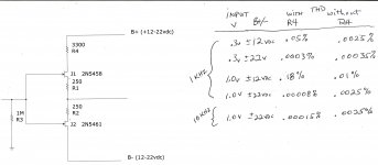
Try this example on your SIMulators. I just built this on a breadboard for laughs but it is interesting and has useful, practicle application--- I mean how cheap is one resistor. These are actual measured values with real transistors and all their quirks;
How many have the right answere? The Question is why does the THD go down when only one resistor is added (R4)? Clue: The value is unique... a pot in place of R4 demonstrates a distinct THD null at the value shown. let me know if you need more clues.
Thx-RNMarsh
Well, cancellation can work across the whole spectrum -
Try this example on your SIMulators. I just built this on a breadboard for laughs but it is interesting and has useful, practicle application--- I mean how cheap is one resistor. These are actual measured values with real transistors and all their quirks;
How many have the right answere? The Question is why does the THD go down when only one resistor is added (R4)? Clue: The value is unique... a pot in place of R4 demonstrates a distinct THD null at the value shown. let me know if you need more clues.
Thx-RNMarsh
Attachments
Last edited:
You can check what I said by connecting the 1k R26 to the negative rail instead. Then plot an FFT of the TIS Ib and then the Ib of the enhancer. They should be basically the same, except for absolute level and the effect of R1 (which responds to Early effect). This should be true whether or not R26 is connected to the rail or the CCS.
I don't argue that the enhancer decreases overall distortion by increasing OLG. However I don't think it improves open-loop linearity and if anything, must hurt it a bit. If your THD is not reduced by the amount of extra loopgain, then this is the natural conclusion. If other distortion mechanisms swamp it, then these actually serve to further worsen linearity. I would assess TIS/OPS linearity by doing a .four of the output current of the LTP.
At 200Hz your THD plots are virtually identical except for H2. How do you explain this? Even if the harmonic spectrum is different, most of the harmonics should be lower. They're not. Are you sure your current mirror is not the dominant source of distortion rather than the TIS/OPS? The fact that the THD "corner" is much higher in the second plot suggests something resistive shunting the loop gain.
You may be right in the effects you observe, but I pointed out the Hfe thing because this should be taken into account. None of the mechanisms you describe could directly result in more linearity, even if more linearity is observed. It must come from some other mechanism. H2 is the main harmonic affected, so this must be the work of a counter-H2 generator. R1 could serve as this as it responds to Early effect and nonlinear Vbe, but I find the lack of reduction of any other harmonics to be highly suspect and doesn't match with an increase in OLG. A saturating current mirror might also provide this effect.
Harmonics cancellation counts as linearization, as an indirect method. However the "line" will be more jagged. You have simply removed the dominant harmonic. You must already understand this since you recognize a non-shunted TIS output takes advantage of the fact that Hfe is typically more linear than Vbe.
Also, C7 is definitely not insignificant. If it has a corner in the audio spectrum then it is probably affecting the THD results.
I may be totally wrong. I will do a simulation if you insist, but I won't be able to get to it today. All of this should be testable however by either of us.
Well, cancellation can work across the whole spectrum -
Try this example on your SIMulators. I just built this on a breadboard for laughs but it is interesting and has useful, practicle application--- I mean how cheap is one resistor. These are actual measured values with real transistors and all their quirks;
How many have the right answere? The Question is why does the THD go down when only one resistor is added (R4)? Clue: The value is unique... a pot in place of R4 demonstrates a distinct THD null at the value shown. let me know if you need more clues.
Thx-RNMarsh
That's interesting. There are several potential distortion mechanisms and not knowing these devices I can't say which one is dominant. It would be helpful to have THD figures for loaded and unloaded with and without R4. It would be interesting to see which harmonics were dominant once the null was reached. If it can maintain low THD at 50% max load, then it's pretty good.
Here's mine:
http://www.diyaudio.com/forums/analogue-source/154210-mpp.html#post3559756
Last edited:
Output Z by feedback or evil shunt?
But for the impedances within a feedback loop and its effects, here's another nugget I got from GG Baxandall.
Let's say you have a VAS for which you have defined the gain by having an evil shunt component on its output. The output Z of the VAS is mainly the Z of that evil shunt component.
You get rid of the evil shunt and arrange feedback around the VAS (eg with plain Miller) to replicate the gain you had with it. If the gain is replicated accurately, you'll find the output Z is also replicated.
This applies exactly with a single device VAS and is usually accurate for enhanced etc up to quite HF too .. enough to make guesses for stability & Open Loop gain. You can even use this on much more complex circuits ... including determining the output Z of a complete amp.
This is of course one basis for the goodness of 'pure Cherry'. The VAS output is kept HiZ so the distortion mechanism for the Class B output is kept low order (hfe mismatch & droop) rather than spiky high order xover with voltage drive. See Self for chapter & verse of the evil THD due to voltage drive.
You see this in any amp converted to 'pure Cherry', even the badly done ones that show small or no improvement in THD. The residual is always less spiky, no Gm doubling and much less dependent on critical biasing.
More pics & examples in Cherry's papers.
As I said, one can consider this is how an emitter follower 'reduces' distortion.The Cjc currents flowing through the enhancer's emitter are copied into its base current, so it doesn't become more linear, it is just diluted to a number of zeros such that other effects may easily swamp it. Inside the feedback loop, source impedance doesn't affect linearity like that; the same current is required to drive the proceeding stage and flows through regardless of it. But you must know this already as you advocate no shunting at the TIS output.
But for the impedances within a feedback loop and its effects, here's another nugget I got from GG Baxandall.
Let's say you have a VAS for which you have defined the gain by having an evil shunt component on its output. The output Z of the VAS is mainly the Z of that evil shunt component.
You get rid of the evil shunt and arrange feedback around the VAS (eg with plain Miller) to replicate the gain you had with it. If the gain is replicated accurately, you'll find the output Z is also replicated.
This applies exactly with a single device VAS and is usually accurate for enhanced etc up to quite HF too .. enough to make guesses for stability & Open Loop gain. You can even use this on much more complex circuits ... including determining the output Z of a complete amp.
This is of course one basis for the goodness of 'pure Cherry'. The VAS output is kept HiZ so the distortion mechanism for the Class B output is kept low order (hfe mismatch & droop) rather than spiky high order xover with voltage drive. See Self for chapter & verse of the evil THD due to voltage drive.
You see this in any amp converted to 'pure Cherry', even the badly done ones that show small or no improvement in THD. The residual is always less spiky, no Gm doubling and much less dependent on critical biasing.
More pics & examples in Cherry's papers.
You misunderstand. Reducing TIS Zout itself does not decrease spikyness. What happens is that whatever you're shunting with, be it Miller or just a cap, conducts the voltage distortion of the OPS which the input stage must then bear. If you were to lower TIS output impedance without adding a leakage path for OPS voltage distortion, then the spiky residual would go away. It is the distortion signal that needs to be rejected, and this is not as simple as piling on buffers, since buffers only address the current distortion, not the voltage distortion.
Furthermore, I have been talking about open-loop linearity, which I thought was what you were talking about. The enhancer no doubt reduces THD, but not TIS linearity unless it is through a mechanism of harmonic cancellation. If you increase loop gain but decrease open-loop linearity by the same amount, it will result in no gain in THD.
Furthermore, I have been talking about open-loop linearity, which I thought was what you were talking about. The enhancer no doubt reduces THD, but not TIS linearity unless it is through a mechanism of harmonic cancellation. If you increase loop gain but decrease open-loop linearity by the same amount, it will result in no gain in THD.
- Home
- Amplifiers
- Solid State
- Bob Cordell's Power amplifier book