Aaarggh! Can open, worms everywhere! 😱😀
I'm so sorry.... You should have ignored me 😉
jan
Aaarggh! Can open, worms everywhere! 😱😀
A note on punctuation: two complete sentences must not be separated with a comma. Use a semi-colon, a full stop or a joining comma with the connecting words and , but, or, while or yet.🙂
This reminds me of the medieval debates about how many angels fit on the head of a pin. My answer has always been What number where you looking for ? Here also rests the amplifier with infinite gain, feedback, bandwidth and thus acceptable phase margins.Which two quantities are approaching infinity at the same rate in an amplifier with infinite gain?
But enough of this: there is no such thing as an amplifier with infinite gain, so why are we debating this? 🙂
Harrydymond,
Understanding that most high precision devices like a resistor are selected, automatically I would think most often, from a wider variance production process I am trying to understand your dislike of the process? Since the larger groups will have a wider variance and therefor normally would be used where that wider variance is allowed why would it matter that the closest center precision devices have been removed?
Good question!
is your dislike because you can no longer purchase the wider tolerance parts and find the close tolerance parts?
Partly yes.
If a manufacturer is able to produce 0.1% toleranced (or whatever) parts "right off the bat" without having to select them from a wider toleranced process, that might suggest that their production process is more sophisticated and reliable. However this is just an assumption/hunch and may not be valid.
I'm only a SPICE newbie...
Alas, senility is catching up on me but one tries one's best. 🙂I know, you poor thing; I KNOW! And from your posts it is abundantly obvious you're a "newbie" at everything else. Really sad for a man of your advanced "Jurassic" years.😀
But but .. its YOU who claim to be a SPICE guru. All your theories & assertions seem to be based on SPICE. Yet your SPICE models ALL seem to have poor THD & stability.And yet you pompously and captiously pontificate about my SPICE simulations as though you are an Authority on the subject...😀
Is it your aim to develop theory and methods that guarantee poor THD & stability 😕
Surely posting, even SPICE world, examples that show good THD & stability rather than cr*p, will give us a better idea of the worth of your methods for 'real life' work? 🙂 I know you spurn 'real life' evidence & work ... but most of us here do dis theory & SPICE sh*t with some 'real life' aim in mind.
______________
Waly, my limited knowledge & experience only allow me small contributions compared to your erudite efforts. eg I'm trying to put together some small examples to help mcd99uk and Zero D. I apologise if you find these ineffective.Waly said:kgrlee, I find your habit of painting the contributors here in various colours, without effectively contributing yourself to the topic (other than references to "jurassic times", and stating your ignorance on various subjects) rather offensive.
I HAVE complimented you when you have enlightened even the unwashed masses like myself.
Surely you're not taking a hump at my 'Excess Phase'? It's just an attempt by insclutable oliental at decadent Western humour. But as you find it offensive, I resolve to use the phrase ONLY in strict Bode/Hilbert terms from now on.
However, please don't fall into the ranks of da pseudo prophets. I note one of them is determined to start yet another huge semantic pedantic argument with no practical use .. except to demonstrate his wonky ...
_____________________
FWIW, Bob Cordell's models consistently gave the worst THD & stability so I'm inclined to believe they are 'better' than the others 🙂
Du..uh! .. and I was so proud of my use of ' ' & 🙂 for dis decadent Western humour 🙁Waly said:I can't think of a more stupid Spice models QA metric.
But but .. its YOU who claim to be a SPICE guru.
And where, precisely, have I claimed to be a "SPICE guru"?😕
Are you even sane?😕
...insclutable oliental...
😱Learn how to spell, for crying out loud!😱
If you measure (with a precision bridege) a batch of 1% resistors from a good maker, you'll find a nice Gaussian distribution. with std dev. easily within 0.1% though the mean may not be within 0.1% of the nominal value. This is how a good manufacturing process should be. A good maker also continuously strives to get the mean to the nominal value.Understanding that most high precision devices like a resistor are selected, automatically I would think most often, from a wider variance production process I am trying to understand your dislike of the process? Since the larger groups will have a wider variance and therefor normally would be used where that wider variance is allowed why would it matter that the closest center precision devices have been removed? If the wider selection matches requirements is your dislike because you can no longer purchase the wider tolerance parts and find the close tolerance parts?
You'll also see this with good NPO/COG ceramics thought the std dev will be rather wider. I've used this to get excellent CM rejection in inexpensive balanced ins & outs .. just using resistors & caps from the same batch.
If you measure a batch of 1% polystyrenes however, you'll probably find a flat top dist. Most makers just select from a larger batch. The process is incapable of producing '1%' parts. Sometimes you see a slanting distribution which means your 'selected' bits are all from one side of the bell curve.
If I'm making speakers, I want them all to have response with a nice Gaussian distribution around the 'standard unit'. I can then argue sensibly with Production over 3 or 4 or 5 std dev. as the acceptance limits.
But if the response has a flat topped distribution, the process is incapable of producing the accuracy I want and we are only arguing over who pays for the rejects.
These issues were really important to me in my previous life .. particularly with xover capacitors.
The Japanese have this down pat which is why you usually find their stuff exceeds their published spec. by a large margin.
I think it is rather evident that Mr. Lee is misspelling intentionally for effect..... I have no problems understanding his English and he is more than welcome here by us Yankee's to educate with his Jurassic knowledge when he thinks it may help those not of the EE persuasion to understand a concept. Perhaps those who are so in opposition to what Mr. Cordell is trying to communicate should write their own books or start their own threads and let's see how well followed those threads become.
Kgrlee,
I understand what you are saying about the Gaussian distribution, I did take statistics, I was just referring to the loose tolerance that some parts seem to have been produced in the past. Carbon resistors come to mind there. I too would want a much tighter tolerance in production wherever that is possible, that would obviously produce a higher value product. Standard capacitors are still in the 10 to 20% range in most film capacitors even though it is again obvious with newer winding machines that this is a rather loose tolerance that is totally unnecessary. Says more about the sloppy work habits of those producers or a lack of attention to quality controls.
Last edited:
If you measure (with a precision bridege) a batch of 1% resistors from a good maker, you'll find a nice Gaussian distribution. with std dev. easily within 0.1% though the mean may not be within 0.1% of the nominal value. This is how a good manufacturing process should be. A good maker also continuously strives to get the mean to the nominal value.
You'll also see this with good NPO/COG ceramics thought the std dev will be rather wider. I've used this to get excellent CM rejection in inexpensive balanced ins & outs .. just using resistors & caps from the same batch.
If you measure a batch of 1% polystyrenes however, you'll probably find a flat top dist. Most makers just select from a larger batch. The process is incapable of producing '1%' parts. Sometimes you see a slanting distribution which means your 'selected' bits are all from one side of the bell curve.
If I'm making speakers, I want them all to have response with a nice Gaussian distribution around the 'standard unit'. I can then argue sensibly with Production over 3 or 4 or 5 std dev. as the acceptance limits.
But if the response has a flat topped distribution, the process is incapable of producing the accuracy I want and we are only arguing over who pays for the rejects.
These issues were really important to me in my previous life .. particularly with xover capacitors.
The Japanese have this down pat which is why you usually find their stuff exceeds their published spec. by a large margin.
I don't suppose you know of any published references for information like this? e.g. academic papers or manufacturer tech. notes.
The message I tried to pass is: naming something assumes some kind of convention - no one calls dog to a cow, because everyone follows the same convention.
In this case, textbooks define Opamp as an electrical component with low (ideally zero) output impedance, and OTA as an electrical component with high (ideally infinite) output impedance.
In the frequency band of interest (more on this below), the two stage opamp has relatively large output impedance, hence it is usually called an OTA.
Yes, but let us then get back to the basic definitions: fundamentally OTAs and Opamps exist for us to apply negative feedback and minimize (ideally make zero) their input voltage. This happens because of the large gain/transconductance or the Opamp/OTA, and is absolutely central in feedback theory.
As you say, the output impedance drops to higher frequencies in the two stage miller compensated amplifier… but so does the gain.
When the output impedance gets to be low enough for it fall in the definition of Opamp, the gain is also pretty low, negative feedback is not being effective anymore, and so you’re out of the frequency band of interest.
Note that I'm not trying to convince you to start calling it an OTA, but rather explain you why there are many (many, many, many people around the world) that do that. At the end of the day, if you model it properly (transconductance of the output transistor connected to the resistance "seen" at the node and the capacitances connected there) the circuit will work no mater what you call it 😉
Very well explained. Your posts are of course totally correct; I could not say it better.
.Nevertheless, I would be interested to examine references where the two stage Miller compensated amplifier is called an "OTA", if you can provide them. Thanks.
Sansen: Analog design essentials ch 5 p 151 and following
p 166 generic two stage opamp: Miller OTA
Ch 6 p 181 and following: systematic design of operational amplifiers:
Table of content
Design of single stage OTA
Design of Miller CMOS OTA
See also Laker and Sansen : ch 6 operational amplifier design
6.2 The Miller CMOS OTA
My pleasure
Thanks JPV. I have read that section, and I am afraid I do not agree with Sansen; I much prefer Solomon's analysis of the two stage Miller compensated amplifier as a voltage amplifier and not an OTA..
Sansen: Analog design essentials ch 5 p 151 and following
It is instructive that other respected authorities such as Grey, Hurst, Lewis and Meyer in their book "Analysis and Design of Analog Integrated Circuits" don't refer to the OTA in this context at all.
Finally, below are links to what I understand to be an OTA:
http://www.uni-bonn.de/~uzs159/ota3080.html
http://users.ece.gatech.edu/~lanterma/sdiy/datasheets/ota/ca3080apnote.pdf
Nothing at all to do with two stage miller compensated amplifiers, I think you'll agree.
Last edited:
If you measure (with a precision bridge) a batch of 1% resistors from a good maker, you'll find a nice Gaussian distribution. with std dev. easily within 0.1% though the mean may not be within 0.1% of the nominal value. This is how a good manufacturing process should be. A good maker also continuously strives to get the mean to the nominal value.
This is really Quality Management 101.I don't suppose you know of any published references for information like this? e.g. academic papers or manufacturer tech. notes.
Perhaps the biggest factor in the rise to dominance of Japanese manufacturing in the 50s & 60s was their adoption of these methods and more importantly, their understanding of these issues. The statistical tools were taught to EVERYONE at a very early age in school.
My experience is that Japanese engineers are always quite surprised to find the rare decadent Western engineer who understood these concepts ..... while the chap who sweeps the floor in a Japanese factory certainly would 🙄
One of my most satisfying experiences was explaining the bell (Gaussian) curve to my Shop Floor Supervisors & Charge Hands and realising they instantly grasped the implications with regard to the parts they had to work with ... and also as a measure of the quality of their own work.
On the other hand, I know Quality Assurance Managers who could quote AQLS, six-sigma and other pedantic stuff in their sleep ... but who didn't have a clue about the implications of a flat top or slanting distribution. You try not to buy from these people as you also wouldn't buy 5% parts from people who supplied you with 'flat top' 1% parts. (Kindhornman's double peaked distribution 😱)
I hope the situation has changed for Western manufacture.
Harry, there will be people in Bristol U who teach this, probably in Manufacturing Technology or something. It will be under Statistical Process Control. Sadly, understanding the concepts as they relate to real life is far more important than being able to do the maths. Many of my Supervisors and Charge Hands didn't finish High School.
There are simple techniques to get around the maths .. but the 'real life' understanding is paramount ... as the pseudo gurus here so clearly demonstrate. 🙂
_______________
Kindhornman, some manufacturing methods are more amenable to process control than others. NPO ceramics do have quite small variance and can probably be pushed towards a nominal. Alas, there is no demand so no incentive for the makers.
But think of how polystyrene caps are made and you'll not be surprised that 1% film caps will often be selected from a large batch.
My knowledge is 20 yrs old so 21st century tech may be a lot better. Certainly, resistors (at least through hole ones) are much improved from da Jurassic carbon sticks.
_______________
ABSOLUTE NONSENSE! Your circuit can't possibly work unless you call it by the correct TLA. [deleted : 2 pgs of references supporting my definitive 8 pg explanation of why my TLA is right nyah! NYAH! while yours is rubbish]pfigueiredo said:At the end of the day, if you model it properly (transconductance of the output transistor connected to the resistance "seen" at the node and the capacitances connected there) the circuit will work no mater what you call it
En u spul 'mater' rong 2! 😱
Last edited:
BTW, my thanks to Kindhornman for his kind remarks.
Its good to find gentlemen & true gurus among decadent Westerners. It wasn't by any chance the ravings of pseudo gurus from the old country that led to the events of 1776? 🙂
Not that I'm implying there are no gentlemen and true gurus in the old country ..
Its good to find gentlemen & true gurus among decadent Westerners. It wasn't by any chance the ravings of pseudo gurus from the old country that led to the events of 1776? 🙂
Not that I'm implying there are no gentlemen and true gurus in the old country ..
You stated
This is incorrect. Amplifiers are not minimum phase.
Usually this is not relevant and they are practically minimum phase.
But for some reasonable amplifiers, not just implausible "straw man" examples, the non minimum phase has a practical impact. In particular it reduces the GM.
http://www.diyaudio.com/forums/soli...lls-power-amplifier-book-369.html#post3546769
Asked you again here -
http://www.diyaudio.com/forums/soli...lls-power-amplifier-book-370.html#post3546905
And here -
http://www.diyaudio.com/forums/soli...lls-power-amplifier-book-372.html#post3547381
And then, after Mike commented that he missed it, reposted it here -
http://www.diyaudio.com/forums/soli...lls-power-amplifier-book-373.html#post3547703
So your statement above is remarkable, to put it politely.
The Spice ASC has been checked against the real amplifier.
It is not perfect, but it is better evidence than other simulations I have seen in DIY audio, mainly due to the work of Toni and Richard Lee to confirm the models and study normally overlooked parasitics.
Best wishes
David
However, I fail to see the relevance for audio amplifier applications. Audio amplifiers are minimum phase, period.
This is incorrect. Amplifiers are not minimum phase.
Usually this is not relevant and they are practically minimum phase.
But for some reasonable amplifiers, not just implausible "straw man" examples, the non minimum phase has a practical impact. In particular it reduces the GM.
I posted evidence here -otherwise, I am still waiting for a shred of proof.
http://www.diyaudio.com/forums/soli...lls-power-amplifier-book-369.html#post3546769
Asked you again here -
http://www.diyaudio.com/forums/soli...lls-power-amplifier-book-370.html#post3546905
And here -
http://www.diyaudio.com/forums/soli...lls-power-amplifier-book-372.html#post3547381
And then, after Mike commented that he missed it, reposted it here -
http://www.diyaudio.com/forums/soli...lls-power-amplifier-book-373.html#post3547703
So your statement above is remarkable, to put it politely.
The Spice ASC has been checked against the real amplifier.
It is not perfect, but it is better evidence than other simulations I have seen in DIY audio, mainly due to the work of Toni and Richard Lee to confirm the models and study normally overlooked parasitics.
Best wishes
David
Kgrlee,
Long before I heard the term Lean and six-sigma I was introduced to SPC by my father who had a medical laboratory. I used these process controls in my own manufacturing facility before moving into aerospace and hearing about nothing but Lean and 6-sigma. Funny how after setting up a complete 6-sigma program for a new Dessault winglet for one of their planes as soon as the program started all that work was so soon forgotten. Out came the mallets and the undersized alignment pins to test the parts on the fixtures and not another word of the months of preparation for the program was spoken of. I actually laughed at my boss the head of engineering when they brought me into a meeting about why the parts weren't fitting and in about two minutes I explained what went wrong with all those simulations and mathematical models. I understood the composites application better than all the so called educated engineers who had never designed a composite part like that and forgot about the shrink factors affecting the part contours.
Long before I heard the term Lean and six-sigma I was introduced to SPC by my father who had a medical laboratory. I used these process controls in my own manufacturing facility before moving into aerospace and hearing about nothing but Lean and 6-sigma. Funny how after setting up a complete 6-sigma program for a new Dessault winglet for one of their planes as soon as the program started all that work was so soon forgotten. Out came the mallets and the undersized alignment pins to test the parts on the fixtures and not another word of the months of preparation for the program was spoken of. I actually laughed at my boss the head of engineering when they brought me into a meeting about why the parts weren't fitting and in about two minutes I explained what went wrong with all those simulations and mathematical models. I understood the composites application better than all the so called educated engineers who had never designed a composite part like that and forgot about the shrink factors affecting the part contours.
Good zeros
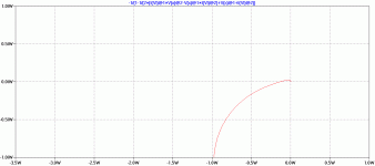
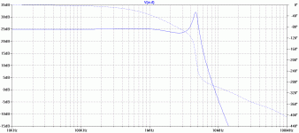
NoC7.gif & NoC7Nyq.gif shows PM & GM are small and Nyquist gets very close to (-1,0) ie dodgy stability. What we need is some +ve phase at the ULGF without adding any amplitude gain.
Making C7 3p9 adds a 'good' zero (minimum phase HF lift) at 4MHz and makes the slope beyond it less steep. 3p9 has about the same reactance as R8, the 10k feedback resistor so starts shorting it out above that frequency and increasing Loop Gain
C7-3p9.gif and C7-3p9Nyq.gif shows much improved PM, GM and the Nyquist curves is further away from (-1,0) ie C7 has improved stability.
This example is just to illustrate the technique. It isn't a fully worked out design though it looks stable with 8R loads. If you try various pure capacitive loads, you'll see peaking. 3n3.gif shows Closed Loop with 3n3 pure capacitance.
This is called 'lead compensation' or 'pole cancellation' by some pedants. I'll leave it to Michael to deal with the semantic issues. 🙂
It's been used in some successful amps, eg the Hitachi MOSFET design circa 1975 (?) IEEE Trans (?) to provide the main compensation ... but IMHO, it is best used in addition to some other scheme providing the main compensation.
Used on its own, its too dependent on device parameters. It doesn't control the Loop Gain directly (like plain Miller, TPC, TMC, 'pure Cherry', MIC etc) ... but introduces a nice tweak to what's already there.
Another useful zero is obtained by decoupling the VAS emitter resistor that Michael despises. Guru Zan points out that the effect of this is more subtle ... but its certainly worth trying if you have a VAS emitter resistor for other reasons ... or even if you haven't 😀
An advantage of these 'good' zeros is that they don't decrease Loop Gain or increase loading so have a less evil effect on THD.
Bob Cordell points out the evils (to do with RF immunity) of using a cap across the feedback resistor in his book.
A good example of this is the small cap across the feedback resistor. This introduces more feedback at HF (ie lift) and if used judiciously, can help stability.
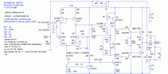
Here's one of Doug Self's models slightly Kiwanuka'd so it shows dodgy stability. Example.asc & Example.gifPlease could you elaborate on this point a little. It would really help my understanding of other concepts if I can get this one.
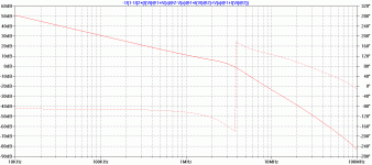
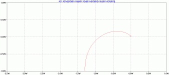
NoC7.gif & NoC7Nyq.gif shows PM & GM are small and Nyquist gets very close to (-1,0) ie dodgy stability. What we need is some +ve phase at the ULGF without adding any amplitude gain.
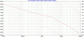
Making C7 3p9 adds a 'good' zero (minimum phase HF lift) at 4MHz and makes the slope beyond it less steep. 3p9 has about the same reactance as R8, the 10k feedback resistor so starts shorting it out above that frequency and increasing Loop Gain
C7-3p9.gif and C7-3p9Nyq.gif shows much improved PM, GM and the Nyquist curves is further away from (-1,0) ie C7 has improved stability.
This example is just to illustrate the technique. It isn't a fully worked out design though it looks stable with 8R loads. If you try various pure capacitive loads, you'll see peaking. 3n3.gif shows Closed Loop with 3n3 pure capacitance.
This is called 'lead compensation' or 'pole cancellation' by some pedants. I'll leave it to Michael to deal with the semantic issues. 🙂
It's been used in some successful amps, eg the Hitachi MOSFET design circa 1975 (?) IEEE Trans (?) to provide the main compensation ... but IMHO, it is best used in addition to some other scheme providing the main compensation.
Used on its own, its too dependent on device parameters. It doesn't control the Loop Gain directly (like plain Miller, TPC, TMC, 'pure Cherry', MIC etc) ... but introduces a nice tweak to what's already there.
Another useful zero is obtained by decoupling the VAS emitter resistor that Michael despises. Guru Zan points out that the effect of this is more subtle ... but its certainly worth trying if you have a VAS emitter resistor for other reasons ... or even if you haven't 😀
An advantage of these 'good' zeros is that they don't decrease Loop Gain or increase loading so have a less evil effect on THD.
Bob Cordell points out the evils (to do with RF immunity) of using a cap across the feedback resistor in his book.
Attachments
ROTFL 😀Long before I heard the term Lean and six-sigma I was introduced to SPC by my father who had a medical laboratory. I used these process controls in my own manufacturing facility before moving into aerospace and hearing about nothing but Lean and 6-sigma. Funny how after setting up a complete 6-sigma program for a new Dessault winglet for one of their planes as soon as the program started all that work was so soon forgotten. Out came the mallets and the undersized alignment pins to test the parts on the fixtures and not another word of the months of preparation for the program was spoken of. I actually laughed at my boss the head of engineering when they brought me into a meeting about why the parts weren't fitting and in about two minutes I explained what went wrong with all those simulations and mathematical models. I understood the composites application better than all the so called educated engineers who had never designed a composite part like that and forgot about the shrink factors affecting the part contours.
As usual, those who pontificate loudest have the least understanding of 'real life'. 🙂
_______________
Some of us ex-colonials, rebel & loyal and other foreigners may be puzzled at the lack of a sense of humour in Waly & MikeK. I can assure you that the majority of POMs do have one ... but very twisted. An example.
The big English excuse to let off fireworks, bonfires etc is Guy Fawkes Night. It commemorates a failed terrorist attempt to blow up the Houses of Parliament. It's like 6/4 celebrates an attempt at 9/11 😱
Last edited:
- Home
- Amplifiers
- Solid State
- Bob Cordell's Power amplifier book
