
I just said
Nico,
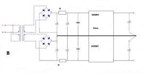
B only suits a single rectifier and the Shunts must be a +ve & -ve pair.
A
divide the value of a single R by two
use identical regulators; i.e., both positive or both negative.
divide the value of a single R by two
use identical regulators; i.e., both positive or both negative.
thanks
now is better the A ,0V at the end ,ie better gnd separation loop on pulse carge of caps and so on
now is better the A ,0V at the end ,ie better gnd separation loop on pulse carge of caps and so on
Interesting read 
A quick thought and came up with this in my head...
Now...
lets hear what you guys think 😎
A quick thought and came up with this in my head...
An externally hosted image should be here but it was not working when we last tested it.
Now...
lets hear what you guys think 😎
Last edited:
Common mode noise?What is the point of L7 ? The currents through it aren't going to be balanced.
Common mode noise?
Used it on a couple of automotive audio amps to remove noise from lines and besicaly cancel out noise.
We know nothing about the load he intend to supplyThe unbalanced currents are going to saturate the choke unless it has a really huge core.
For a ClassA amplifier that psu is ok.
The unbalanced currents are going to saturate the choke unless it has a really huge core.
Core is quite large ( used to be a 300VA toroid )
We know nothing about the load he intend to supply
For a ClassA amplifier that psu is ok.
Going to drive a class AB using LME49811 as interface and 5 pairs of thermall tracks 😎
Core is quite large ( used to be a 300VA toroid )
Pardon me for going off half-cocked!
I assumed a ferrite core.
In any case, wouldn't a common mode choke be better placed at the input of the PSU ?
Interesting read
A quick thought and came up with this in my head...
Now...
lets hear what you guys think 😎
A small point - the LEDs are reversed
A small point - the LEDs are reversed
thanks for pointing that out...
its been a long day and it took me a whole 5 mins to draw that up.
what does L5C17 do?
the centre tapped transformer cannot drive the dual rectifier PSU.
What if the currents from the two rails are not identical? Eg driving a ClassA push/pull amplifier.
the centre tapped transformer cannot drive the dual rectifier PSU.
What if the currents from the two rails are not identical? Eg driving a ClassA push/pull amplifier.
what does L5C17 do?
the centre tapped transformer cannot drive the dual rectifier PSU.
What if the currents from the two rails are not identical? Eg driving a ClassA push/pull amplifier.
I think it is to suck out the ripple in a certain freq band 😉 , (2kHz?) although the two 3mH coils are in series and could be replaced by a single 6mH. Of course then the diagram doen't look symmetrical anymore.😀
BTW Is there a special reason to use two bridges instead of one?
jd
Last edited:
I think it is to suck out the ripple in a certain freq band 😉 , (2kHz?) although the two 3mH coils are in series and could be replaced by a single 6mH. Of course then the diagram doesn't look symmetrical anymore.😀
The unit i will be using has 2 independent potted 3mH coils in it 😛
BTW Is there a special reason to use two bridges instead of one?
jd
Ease of implementation and use + the fact that i would know if one of my rails goes out its a simple and cheap replacement ( eve though it wont happen as i will be using 50A bridges )
A well designed amp is as good as its power supply!
In the end you can only make as much power as the power supply puts out.
Working on PS Rev 2 as of right now...
- Status
- Not open for further replies.
- Home
- Amplifiers
- Solid State
- Bob Cordell Interview: Power Supplies