Cascode
Hi Bob,
I'm still not totally clear as to how cascoding takes care of the early voltage.
Can you explain this in more detail?
Hi Bob,
I'm still not totally clear as to how cascoding takes care of the early voltage.
Can you explain this in more detail?
This is very likely if this high global feedback poweramp is made with bad output stage. The problematic section is output stage, but the troubleshooting is made in differential pair+VAS, building huge OL gain in these front stage. It's like a car having problem in the tyres, but you keep fixing the steering wheel. Not shooting the real problem.
Better to have good output stage first (like using classA or using EC) and then using suitable gain front stage than building bad output stage with enormous front end gain.
I agree very much on this; most often the work of speeding up the vas is nulled again by applying a relatively high Cdom from output to input, just to slow the whole input down again to match the slower output stage.
Hi keantoken,
I came up with the snubber idea in my MOSFET power amplifier with error correction. I don't recall having used it in BJT output stages, although it might be useful there as well. I refer to them as gate zobel networks on page 226 of my book in the MOSFET chapter, but unfortunately do not show a schematic there with them. I cite as a reference my MOSFET amplifier paper. That paper is available on my website at CordellAudio.com - Home.
The basic idea is to damp out resonances that can be part of forming an oscillator topology, such as a Hartley or Colpitts. The technique may very well work with BJT arrangements as well. Don't rule out the possibility it is the drivers oscillating.
It was a little unclear whether the problem you saw was in simulation or prototype, but it sounds like the latter. In that case, Triples of any type can be susceptible to power supply wiring inductances and HF feedback through the power rails. When using ordinary thriple EFs, I often recommend some small-resistance R-C filtering in the rail as it travels back to the driver and thence the pre-driver (i.e., two LPF stages, often with resistances on the order of 1 ohm and 10 ohms, respectively). If the shunt capacitors are of a moderate value, the R-C combination not only acts as an LPF, but also acts as a Zobel on the rails. Cheers, Bob
I don't understand this term:
ordinary thriplet EFs (= triplett emitter followers)
There is a very large difference between the true complementary triplet follower (Harman's "T-Circuit") or quasi complementary triplet (Quad triplet) emitter followers.
In case of so called "true complementary" triplet (super ß) emitter follower (one stage more than ordinary darlington) - in the kind like mentioned by the paper
"An Ultra-Low Distortion Direct-Current Amplifier"
about
http://www.aes.org/tmpFiles/elib/20121003/1091.pdf
or about the attachments by post #15 about
http://www.diyaudio.com/forums/soli...ologies-100ma-idle-sound-closest-class-2.html
you are right in your explanation. Until now I was always successful with this steps
But the situation at quasi complementary triplets is completly different because the right steps to remove unwanted oscillations must be also "Quasi Complementary", this means not a mirror image between the positive and the negative half.
read post #20 about
http://www.diyaudio.com/forums/solid-state/113943-quad-303-triple-cascade-2.html#post2103059
and have a look to post #21, third file (QuadTriple) about
http://www.diyaudio.com/forums/solid-state/113943-quad-303-triple-cascade-3.html
so as pdf file attachment post #22 (EQUIN super ß emitter follower from German's magazine "ELEKTOR") about
http://www.diyaudio.com/forums/solid-state/165165-edwin-20-watt-elektor-1970-may-3.html
I am looking for an appropriate design rule to remove any unwanted oscillations for the various quasi complementary triplett topologies. This I haven't find until know.
Perhaps you know basic articles about the compensation of such three stage super ß quasi complementary stages.
I know too few English keywords therefore. I recall, that I have read some years ago a JAES article regarded that. But I don't know the headline.
Last edited:
The best I can come up ith is that if you reduce the oscillation to a negative resistance in parallel ith a resonator, hich describes most oscillators, and then selectively cancel the negative resistance ith a positive resistance such as an RC snubber, then you've succeeded. There is also the concept of altering parasitics so that the resonance is out of range of the negative impedance. Every technique used to quell local output stage oscillation must be one of these. Phase shift oscillators don't necessarily yield to this analysis, but I am not really a math guru so hat do I kno.
I may have already done this, if I had found a good description of the parasitics around a modern poer BJT folloer that oscillates and that I can simulate successfully. So far I'm having difficulty getting that 50MHz resonance... Perhaps it is a driver that as oscillating.
I may have already done this, if I had found a good description of the parasitics around a modern poer BJT folloer that oscillates and that I can simulate successfully. So far I'm having difficulty getting that 50MHz resonance... Perhaps it is a driver that as oscillating.
Yes, this is a real prototype. I simulated it and then built it. I have a 40MHz signal generator so I have some indication hen simulations and reality don't converge.
Thanks for the info. I onder if I coul find the source of the oscillation by probing the air around the traces. I suppose this ould be a job better suited for an FET probe, unfortunately I don't have one.
Hi Keantoken,
I'm sorry for being late to getting back to you. I wouldn't think probing the iar around the traces would be very effective. Tracking these things down can be difficult. If you haven't tried it, tray base stoppers fir the driver transistors. If you have base stoppers for the output transistors, try probing on both sides of them to see the amplitude of the oscillation. BTW, sometimes just probing with a 10pF 10:1 probe on a sensitive node can stop the oscillation.
Cheers,
Bob
Yes, I'm aware of the difficulties. My scope has about 180pF probe capacitance counting the probe and scope, which makes it totally useless for probing anything but the power supply and output.
I think that a low-Cob active FET probe, with a special insulated frilly tip to maximize surface area, may be able to probe traces through the air. This is because the capacitive input impedance, in series with the capacitance through the air, would form a voltage divider just like resistors would. It would only be an approximate probe at LF because of the lopass needed and the varying probe gain with trace proximity. Nonlinear capacitance would need to be cascoded away to increase the accuracy and sensitivity.
The 150p/47R RC stopped oscillation at 50MHz. Then I discovered oscillation at 150MHz! But, this oscillation remains even when I turn off my amp... How confusing. I wonder who is transmitting!?
Yesterday I shorted the output of my amp into the positive rail, and blew my bench fuse. At 63V variac, 2A gives 120W, which through the trafo becomes 3.4A drawn from the supply. My amp's protection limited it to 5 or 6A, so max instantaneous dissipation of 210W. I am glad to say the protection worked even in this extreme case. I replaced the fuse and turned it on again and it works.
After I get the oscillation sorted out my next order of business will be the thermal compensation. There appears to be thermal positive feedback. If I turn the bias up too fast, it will go up and up and up over time, and if I set it slowly, it will eventually drift down to 30mA or so and then stay there.
Bob Cordell Interview: Negative Feedback
AKSA
“Distortion specs are normally given steady state, sinusoidal, constant frequency. The technology is not presently able to give such measures with real world signals. Carver is in fact nulling dynamic distortion with real music, one of the great unknowns. He is using a subtraction process between two amplifiers to isolate the error 'sound', and tweaking until it is 50-70dB below the line signal.”
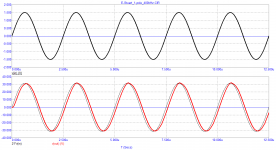
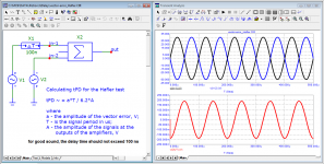
Presumably, Carver uses the Hafler test, which I have already quoted along with the Baxandall test.
What is the attenuation of the vector error signal by 50 ... 70 dB. This means that the level of the vector error is 300 ... 3000 times less than the signals at the outputs of the amplifiers. Let's imagine that we use a triangular signal with a frequency of 10 kHz (100 μs period) as a test signal, while its amplitude at the outputs of the amplifiers is 60 V from peak to peak. If the signals at the outputs of the amplifiers are equal, the difference signal will be a rectangular signal with an amplitude of 0.2 to 0.02 V.
Time Propagation Delay is calculated by the formula:
tPD = aT / 4A
where
a - is the amplitude of the rectangular signal at the load;
T - is the period of the triangular signal;
A - amplitude of the triangular signal at the outputs of the amplifiers
In this case
tPD (max) = 0.2 * 100/4 * 60 = 20/240 = 0.083 μs = 83 ns
tPD (min) = 0.02 * 100/4 * 60 = 2/240 = 0.0083 μs = 8.3 ns
I have repeatedly mentioned that the signal propagation delay time should not exceed 100 ns. As you can see, Carver is doing just that.
AKSA
“Distortion specs are normally given steady state, sinusoidal, constant frequency. The technology is not presently able to give such measures with real world signals. Carver is in fact nulling dynamic distortion with real music, one of the great unknowns. He is using a subtraction process between two amplifiers to isolate the error 'sound', and tweaking until it is 50-70dB below the line signal.”
Presumably, Carver uses the Hafler test, which I have already quoted along with the Baxandall test.
What is the attenuation of the vector error signal by 50 ... 70 dB. This means that the level of the vector error is 300 ... 3000 times less than the signals at the outputs of the amplifiers. Let's imagine that we use a triangular signal with a frequency of 10 kHz (100 μs period) as a test signal, while its amplitude at the outputs of the amplifiers is 60 V from peak to peak. If the signals at the outputs of the amplifiers are equal, the difference signal will be a rectangular signal with an amplitude of 0.2 to 0.02 V.
Time Propagation Delay is calculated by the formula:
tPD = aT / 4A
where
a - is the amplitude of the rectangular signal at the load;
T - is the period of the triangular signal;
A - amplitude of the triangular signal at the outputs of the amplifiers
In this case
tPD (max) = 0.2 * 100/4 * 60 = 20/240 = 0.083 μs = 83 ns
tPD (min) = 0.02 * 100/4 * 60 = 2/240 = 0.0083 μs = 8.3 ns
I have repeatedly mentioned that the signal propagation delay time should not exceed 100 ns. As you can see, Carver is doing just that.
Bob Cordell Interview: Negative Feedback
Graham Maynard
This is what I mean by the reactive nature of Edmonds arrangement.
We should be aiming for a flat phased damping response.
I also decided to type in the model and see how it works.
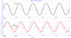
I was not satisfied with the work of TMC. Therefore, I decided to simplify the circuit as much as possible and raise the frequency of the first pole above the audio range as recommended by Matti Otala. As a result, the noise floor in the soundband in the IMD test decreased by almost 20 dB (almost 10 times). The signal transmission delay time has decreased by about 3 times. The output impedance is constant throughout the entire audio band. The slew rate of the output voltage has increased.
Graham Maynard
This is what I mean by the reactive nature of Edmonds arrangement.
We should be aiming for a flat phased damping response.
I also decided to type in the model and see how it works.
I was not satisfied with the work of TMC. Therefore, I decided to simplify the circuit as much as possible and raise the frequency of the first pole above the audio range as recommended by Matti Otala. As a result, the noise floor in the soundband in the IMD test decreased by almost 20 dB (almost 10 times). The signal transmission delay time has decreased by about 3 times. The output impedance is constant throughout the entire audio band. The slew rate of the output voltage has increased.
Attachments
-
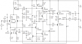 01_TMC_Stuart_SCH.png33.1 KB · Views: 428
 -
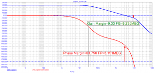 004_E-Stuart_1pole_Loop-Gain.png31 KB · Views: 258
 -
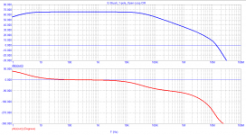 003_E-Stuart_1pole_Open-Loop.png21.6 KB · Views: 185
 -
 002_E-Stuart_1pole_Bode.png25.1 KB · Views: 243
 -
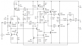 001_E-Stuart_1pole_SCH.png32.4 KB · Views: 250
 -
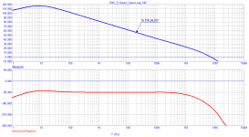
 06_TMC_Stuart_20kHz-Rout.png21.8 KB · Views: 219
 -
 05_TMC_Stuart_TIM.png25.1 KB · Views: 364
 -
 04_TMC_Stuart_IMD_19-20kHz.png28.2 KB · Views: 339
 -
 03_TMC_Stuart_Open-Loop.png23.4 KB · Views: 352
 -
 02_TMC_Stuart_Bode.png22.3 KB · Views: 423
As for the frequency of the first pole, apart from Bruno
John Curl's Blowtorch preamplifier part II
Douglas Self writes about it in the fifth edition
With regard to increasing the frequency of the first pole, the following methods are used:
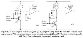
include the load resistor at the VAS output to the common one, i.e. parallel to the VK input. This stabilizes the VAS load and thus reduces the dynamic distortion caused by the amplifier load impedance swings. When using the Darlington triple, the load resistor can be of a large value and additionally does not load the VAS;
include a resistor in parallel with the Cdom condensate as shown in the fifth edition of Douglas Self's book;
and finally, a nested NFB loop is introduced from the VAS output to the NFB summation point. Such a nested FB loop reduces and stabilizes the VAS output impedance (even in the open circuit of the Global NFB loop), and also stabilizes the OPS input impedance, since it is essentially connected in parallel to its input.
John Curl's Blowtorch preamplifier part II
Douglas Self writes about it in the fifth edition
With regard to increasing the frequency of the first pole, the following methods are used:
include the load resistor at the VAS output to the common one, i.e. parallel to the VK input. This stabilizes the VAS load and thus reduces the dynamic distortion caused by the amplifier load impedance swings. When using the Darlington triple, the load resistor can be of a large value and additionally does not load the VAS;
include a resistor in parallel with the Cdom condensate as shown in the fifth edition of Douglas Self's book;
and finally, a nested NFB loop is introduced from the VAS output to the NFB summation point. Such a nested FB loop reduces and stabilizes the VAS output impedance (even in the open circuit of the Global NFB loop), and also stabilizes the OPS input impedance, since it is essentially connected in parallel to its input.
Attachments
Last edited:
Bob Cordell Interview: Negative Feedback
Graham Maynard
This is what I mean by the reactive nature of Edmonds arrangement.
We should be aiming for a flat phased damping response.
I also decided to type in the model and see how it works.
I was not satisfied with the work of TMC. Therefore, I decided to simplify the circuit as much as possible and raise the frequency of the first pole above the audio range as recommended by Matti Otala. As a result, the noise floor in the soundband in the IMD test decreased by almost 20 dB (almost 10 times). The signal transmission delay time has decreased by about 3 times. The output impedance is constant throughout the entire audio band. The slew rate of the output voltage has increased.
You are replying the 9-year old thread. Apparently, me too...😱
From the schematics you posted. There are couple of things changed. To fully understand what change contributes to lower distortion, you have to isolate those changes.
1. TMC is changed to simple Miller compensation. Maybe the original TMC is sub-optimized, and causes more distortion.
2. The equivalent Miller cap value is changed from 120p to 22p. More feedback around output stage, lower distortion value is expected.
3. The way you put R26 is different than the one mentioned in the book. You include input stage as well. It may help lower distortion of input stage a little bit, if there is any.
Last edited:
Hi Petr,Bob, translate this material and read carefully, I hope you find something for your future books
Thanks for bringing this to my attention, but I don't know how to translate it. What is the topic and what are the findings?
Cheers,
Bob
Hi Bob,
Title: "Measuring Distortion in Amplifiers"
Intro: "I have often been asked to define "velocity distortion". I hope this material will help you understand what I'm putting into it.
Concept. A. Petrov. "
Please go to: https://translate.google.com/ for translation of the whole article.
Cheers, E.
Title: "Measuring Distortion in Amplifiers"
Intro: "I have often been asked to define "velocity distortion". I hope this material will help you understand what I'm putting into it.
Concept. A. Petrov. "
Please go to: https://translate.google.com/ for translation of the whole article.
Cheers, E.
The article appears to be a review of various approaches to measuring distortion, including using the notch filters (as in Bob's 1981 THD Analyser), subtraction of the test signal with phase compensation (as in Bob's Distortion Magnifier), "Carver's challenge" and David Hafler's SWDT. In the context of SWDT, the author seems to be making the point that any non-minimal-phase delay in the device-under-test would not allow to fully null the test signal (duh). He further states that group delay should be small, supporting it by simulations of an amplifier's response to non-bandlimited stimulus such as triangle wave.
It kind of reminds of the 1987 Stereophile discussion of the merits of SWDT:
It kind of reminds of the 1987 Stereophile discussion of the merits of SWDT:
David Hafler said:...in addition to low distortion, the amplifier must have wide bandpass and relatively low phase shift. Of course, we will never see the perfect amplifier with infinite null on the SWDT. However, when our null exceeds 60dB over a wide spectrum, I contend that the aberrations are essentially inaudible; an amplifier with different sonic qualities is less accurate.
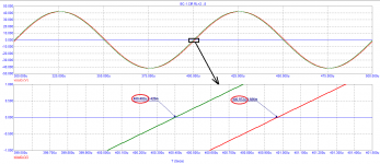
In magnetic recording, there is such a thing as detonation associated with a chaotic change in the speed of the magnetic tape, leading to frequency modulation in the frequency range of 0.2 ... 200 Hz. Hearing is most critical to frequency modulation at a frequency of 4 Hz. Permissible detonation level for tape recorders of the highest group - no more than + -0.08%.
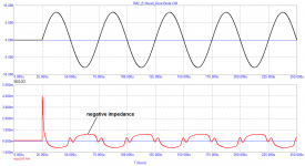
In amplifiers, frequency modulation is also possible as a result of the deviation of the Miller capacitance in the output stage of the VAS under the influence of a change in Ku due to a change in the load impedance. The mechanism of occurrence of frequency modulation was described in one of the articles by Barry Gilbert.
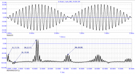
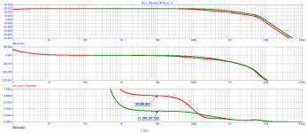
Here is the result of changing the group delay in small-signal mode with the BC-1 amplifier operating at a load of 2 and 8 ohms, as well as changing the signal transit time at a frequency of 10 kHz at the same load.
It can be seen that the group delay deviation is approximately the same in the low-signal mode, which is at full output power and is approximately 570 ns with a signal period of 100 μs.
If we take half of this value, then we can say with confidence that the frequency modulation will be up to 0.25% or more.
Bob, what level of frequency modulation do you think is acceptable?
Best regards
Petr
In amplifiers, frequency modulation is also possible as a result of the deviation of the Miller capacitance in the output stage of the VAS under the influence of a change in Ku due to a change in the load impedance. The mechanism of occurrence of frequency modulation was described in one of the articles by Barry Gilbert.
Here is the result of changing the group delay in small-signal mode with the BC-1 amplifier operating at a load of 2 and 8 ohms, as well as changing the signal transit time at a frequency of 10 kHz at the same load.
It can be seen that the group delay deviation is approximately the same in the low-signal mode, which is at full output power and is approximately 570 ns with a signal period of 100 μs.
If we take half of this value, then we can say with confidence that the frequency modulation will be up to 0.25% or more.
Bob, what level of frequency modulation do you think is acceptable?
Best regards
Petr
Attachments
Hi petr_2009,
Do you have any idea about what you are talking about????In magnetic recording, there is such a thing as detonation associated with a chaotic change in the speed of the magnetic tape ...
I worked in the music industry calibrating studio and consumer tape machines for years. No.
Phase changes are FM modulation. You are talking about poor selections of capacitors right now. This does not occur if you use the correct part, so why are we talking about it?
-Chris

- Home
- Amplifiers
- Solid State
- Bob Cordell Interview: Negative Feedback