Hmmm, it seems to work fine for wine tasting.
(scored 9 out of 10 today, w00t!!!)
In all seriousness, pressure is the easiest thing to eliminate in a blind test. But we diverge from the topic...
(scored 9 out of 10 today, w00t!!!)
In all seriousness, pressure is the easiest thing to eliminate in a blind test. But we diverge from the topic...
I would like to propose a moratorium on all discussion of double-blind or ABX testing of audio equipment until somebody ponies up the large cash (>$100,000) to properly conduct such tests. Until then, all arguments are moot. Anyone here affiliated with a large university that may show some interest?
John
John

Glen,
Cut the personal attacks out completely. They will not be tolerated. You can be abrasive to deal with, and this does not look good on you.
I have deleted your post. Nothing there to forward any discussion.
-Chris
Re: CFB clamp
Hey man, I'm interested 🙂 A 50W amp doesn't represent the begining and end of power amplifier design in general in my eyes either. I too wouldn't bother posting it here - this is clearly the new opamp-sound, DBT VS subjectivism and soul-pleasure thread.
Can you at least drop the URL for the new webpage you are working on though?
Cheers,
Glen
Edmond Stuart said:
Hi David,
Thank you. As a matter of fact, I'm reluctant to drop a schematic of the FB clamp on this forum, as it seems that nobody, except you, shows any interest in a better (and foolproof) clamp. Apparently, people are only interested in their own designs, even when these designs are outdated by more than a quarter of a century.
At the moment, I'm building another website, comprising not only the PGP amp, but also some background info and less complex alternatives, which will include the CFB clamp as well.
Cheers, Edmond.
Hey man, I'm interested 🙂 A 50W amp doesn't represent the begining and end of power amplifier design in general in my eyes either. I too wouldn't bother posting it here - this is clearly the new opamp-sound, DBT VS subjectivism and soul-pleasure thread.
Can you at least drop the URL for the new webpage you are working on though?
Cheers,
Glen
Well there was some discussion of negative feedback going on before the diversion
I did post a sim suggesting that there is another "side" of the box that Otala didn't push on
the sim shows the (wrongly?) preferred flat loop gain over the "audio" range (scaled by my lazy order of magnitude time const) but with a loop gain boost from a region of 2nd order slope that adds a fairly innocuous amount of phase shift without changing loop gain intercept:
60 dB tanh distortion reduction for 20 dB gain boost seems like a good deal to me
I find it hard to worry that the high gain IM products at 15,17KHz are likely pure "phase modulation" distortion at -120 dB down
I did post a sim suggesting that there is another "side" of the box that Otala didn't push on
the sim shows the (wrongly?) preferred flat loop gain over the "audio" range (scaled by my lazy order of magnitude time const) but with a loop gain boost from a region of 2nd order slope that adds a fairly innocuous amount of phase shift without changing loop gain intercept:
jcx said:I think this sim is a OK "sandbox" for playing with tanh input distortion and loop gain, tanh = idealized bjt diff pair gm distortion
G1 is a single pole gain stage with 10 Mrad/s unity gain frequency, call it 1.6 Mhz
Loop gain of G1 stage is 40dB giving ~ 16 KHz loop gain corner
the E1 VCVS takes the input and gives a single ended diff - which is then distorted in the B1 source
parameter k adjusts the tanh scale factor while keeping the 0 V slope constant at 1
I hand trimmed k to give -40 dB HD3 with 16KHz @ 1.41 V input to the loop ( 0 dB in LtSpice) with only the single pole G1 loop gain
then IMD is probed with 1:1 1 KHz, 16KHz that sum to the same 1.41 V peak that gives 1% distortion with single pole gain
R4,5 selects between the single pole response of G1 and a 2-pole response with the added 20 dB gain of G2
the Green traces are the single pole results, the yellow is the 2-pole
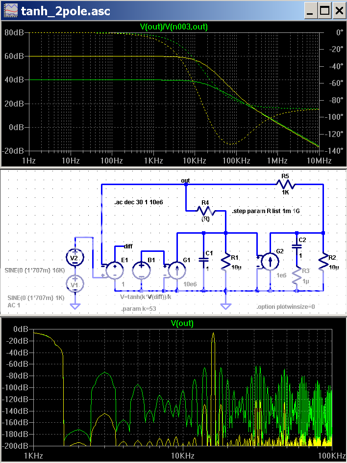
top is loop gain
bottom shows the huge distortion reduction that comes from simply 20 dB more gain
60 dB tanh distortion reduction for 20 dB gain boost seems like a good deal to me
I find it hard to worry that the high gain IM products at 15,17KHz are likely pure "phase modulation" distortion at -120 dB down
Attachments
Nelson Pass said:
Yes, very much so.
... and then there is the school that says that people perform best when under pressure

Sorry for the OT. I'll stay out of DB from now on in this thread. But is was a good discussion, anyway.
Jan Didden
Re: CFB clamp
Edmond,
Just because (in my case) the comments have been minimal doesn't
mean your input has not been well received.
To the contrary - your pgp and the various design components
of it such as the CMCL have been a real technical tour de force.
Good stuff.
cheers
Terry
Edmond Stuart said:
Hi David,
Thank you. As a matter of fact, I'm reluctant to drop a schematic of the FB clamp on this forum, as it seems that nobody, except you, shows any interest in a better (and foolproof) clamp. Apparently, people are only interested in their own designs, even when these designs are outdated by more than a quarter of a century.
At the moment, I'm building another website, comprising not only the PGP amp, but also some background info and less complex alternatives, which will include the CFB clamp as well.
Cheers, Edmond.
Edmond,
Just because (in my case) the comments have been minimal doesn't
mean your input has not been well received.
To the contrary - your pgp and the various design components
of it such as the CMCL have been a real technical tour de force.
Good stuff.
cheers
Terry
CFB clamp
Hi David,
By CMCL you mean, of course, the FB clamp. This morning I've tried to simulate that on a simple 3-stage amp (by D. Self), but the result was negative. During clipping (and clamping), small oscillations appeared at 9MHz. So I concluded that the traditional LTP produces too much phase shift to safely allow feedback from the VAS output to the inverting input of the LTP. As a matter of fact, even with a much faster CFB input stage, it was pretty tricky to get the CFB clamp sufficiently stable.
Cheers, Edmond.
lumanauw said:Hi, Edmond,
Can CMCL be placed in VAS of ordinary 3stages power amp? I think it does a better job than diode array (soft clipping in NAD3020) or conventional baker clamp.
Hi David,
By CMCL you mean, of course, the FB clamp. This morning I've tried to simulate that on a simple 3-stage amp (by D. Self), but the result was negative. During clipping (and clamping), small oscillations appeared at 9MHz. So I concluded that the traditional LTP produces too much phase shift to safely allow feedback from the VAS output to the inverting input of the LTP. As a matter of fact, even with a much faster CFB input stage, it was pretty tricky to get the CFB clamp sufficiently stable.
Cheers, Edmond.
Re: CFB clamp
Hi Edmond,
That is one of the idiosyncracies of the forum world. You ask: anybody interested in such-and-such", and only luke-warm, if any, replies. But if you post your design, we all jump on it. For better or worse. 😉
Jan Didden
Edmond Stuart said:[snip][Apparently, people are only interested in their own designs, even when these designs are outdated by more than a quarter of a century.[snip]Cheers, Edmond.
Hi Edmond,
That is one of the idiosyncracies of the forum world. You ask: anybody interested in such-and-such", and only luke-warm, if any, replies. But if you post your design, we all jump on it. For better or worse. 😉
Jan Didden
Re: Re: CFB clamp
Hi Terry,
Thank you for your appreciative words.
Cheers, Edmond.
Terry Demol said:
Edmond,
Just because (in my case) the comments have been minimal doesn't
mean your input has not been well received.
To the contrary - your pgp and the various design components
of it such as the CMCL have been a real technical tour de force.
Good stuff.
cheers
Terry
Hi Terry,
Thank you for your appreciative words.
Cheers, Edmond.
Re: CFB clamp
Edmond is right about the importance of good clamping circuitry. On material with good dynamic range, I think that amplifiers clip more often than we think, especially when amplifiers of modest power drive less efficient speakers. We demonstrated this at the RMAF2006 and HE2007 audio workshops. We had a Rickey Lee Jones cut that was played at an average power level of 1-2 watts that was peaking at 250 watts. This was with 84 dB SPL speakers playing at realistic, but certainly not uncomfortable levels in a hotel room. See the RMAF and HE2007 Listening and Measurement workshop writeups on my web site at www.cordellaudio.com.
I think Tom Holman was one of the first to make good use of a Baker Clamp in an audio amplifier. IIRC, he ran the VAS off of a boosted supply and the clamp diode prevented the output of the VAS from going beyond the main rail voltage, keeping the VAS and the output stage out of saturation. Since the clamp diode was connected to the main rail voltage, the clamping voltage appropriately tracked the available main rail voltage, so that dynamic headroom was not lost.
I’ve used a variation of this in some of my amplifiers that I refer to as a “Flying Baker Clamp”. Normally a Baker Clamp diode sees the full p-p signal swing and its capacitance variation can cause some high-frequency nonlinearity at the output node of the VAS. What we would like is a clamp diode arrangement wherein under normal signal conditions both sides of the diode are moving equally with the signal, so that a high voltage diode is not needed and junction capacitance variation is minimized.
When we do this, the clamp diode is referred to as “flying”. The side of the diode that would normally go to a clamp reference voltage instead goes to a buffered replica of the signal voltage through a resistor. That buffered replica signal is then clamped with a conventional clamp diode, stopping the replica from moving with signal when the clip point is reached. The flying Baker clamp diode then clips the VAS output signal. The clip reference for the conventional clamp diode can be made to track the available main rail voltage so that it is adaptive.
In some simpler designs, I’ve used what I call “flying catch” diodes. These diodes are essentially connected from each end of the VAS bias spreader to the output node, so they also “fly” with the signal. In this arrangement, when the output stage clips and the output node stops moving, these flying catch diodes prevent the VAS node from moving more than a certain amount of voltage beyond the clipping point, preventing saturation and controlling recovery time. When properly arranged, these diodes also can act as a natural current limiter on the output stage. The use of flying catch diodes is described briefly on my website at www.cordellaudio.com in the Athena active loudspeaker Power Point presentation under the Loudspeaker tab.
The design of clamping arrangements is, of course, usually highly dependent on the details of the VAS, driver and output stage designs.
Cheers,
Bob
Edmond Stuart said:
Hi David,
Thank you. As a matter of fact, I'm reluctant to drop a schematic of the FB clamp on this forum, as it seems that nobody, except you, shows any interest in a better (and foolproof) clamp. Apparently, people are only interested in their own designs, even when these designs are outdated by more than a quarter of a century.
At the moment, I'm building another website, comprising not only the PGP amp, but also some background info and less complex alternatives, which will include the CFB clamp as well.
Cheers, Edmond.
Edmond is right about the importance of good clamping circuitry. On material with good dynamic range, I think that amplifiers clip more often than we think, especially when amplifiers of modest power drive less efficient speakers. We demonstrated this at the RMAF2006 and HE2007 audio workshops. We had a Rickey Lee Jones cut that was played at an average power level of 1-2 watts that was peaking at 250 watts. This was with 84 dB SPL speakers playing at realistic, but certainly not uncomfortable levels in a hotel room. See the RMAF and HE2007 Listening and Measurement workshop writeups on my web site at www.cordellaudio.com.
I think Tom Holman was one of the first to make good use of a Baker Clamp in an audio amplifier. IIRC, he ran the VAS off of a boosted supply and the clamp diode prevented the output of the VAS from going beyond the main rail voltage, keeping the VAS and the output stage out of saturation. Since the clamp diode was connected to the main rail voltage, the clamping voltage appropriately tracked the available main rail voltage, so that dynamic headroom was not lost.
I’ve used a variation of this in some of my amplifiers that I refer to as a “Flying Baker Clamp”. Normally a Baker Clamp diode sees the full p-p signal swing and its capacitance variation can cause some high-frequency nonlinearity at the output node of the VAS. What we would like is a clamp diode arrangement wherein under normal signal conditions both sides of the diode are moving equally with the signal, so that a high voltage diode is not needed and junction capacitance variation is minimized.
When we do this, the clamp diode is referred to as “flying”. The side of the diode that would normally go to a clamp reference voltage instead goes to a buffered replica of the signal voltage through a resistor. That buffered replica signal is then clamped with a conventional clamp diode, stopping the replica from moving with signal when the clip point is reached. The flying Baker clamp diode then clips the VAS output signal. The clip reference for the conventional clamp diode can be made to track the available main rail voltage so that it is adaptive.
In some simpler designs, I’ve used what I call “flying catch” diodes. These diodes are essentially connected from each end of the VAS bias spreader to the output node, so they also “fly” with the signal. In this arrangement, when the output stage clips and the output node stops moving, these flying catch diodes prevent the VAS node from moving more than a certain amount of voltage beyond the clipping point, preventing saturation and controlling recovery time. When properly arranged, these diodes also can act as a natural current limiter on the output stage. The use of flying catch diodes is described briefly on my website at www.cordellaudio.com in the Athena active loudspeaker Power Point presentation under the Loudspeaker tab.
The design of clamping arrangements is, of course, usually highly dependent on the details of the VAS, driver and output stage designs.
Cheers,
Bob
Re: Re: CFB clamp
Hello Bob,
You and Edmond are surely taxing our imagination, what with discussions of circuits without any diagrams....
A question: assuming you have a clamp to prevent the Vas to overdrive the output stage. Because of the negative feedback (I assume this is a 'classical' nfb amplifier), at clipping, you are still heavily overdriving the input stage of the amp, and thus everything following, right up until the Vas. I know that the Vas and input stage probably come out of overdrive quicker than the output stage, but still, it seems only a partial solution. That is one reason why some of us have been impatiently looking for info on your Klever Klipper. Are you ready to lift (part of) the veil? 😉
Jan Didden
Bob Cordell said:[snipped to preserve bandwidth]The design of clamping arrangements is, of course, usually highly dependent on the details of the VAS, driver and output stage designs.
Cheers,
Bob
Hello Bob,
You and Edmond are surely taxing our imagination, what with discussions of circuits without any diagrams....
A question: assuming you have a clamp to prevent the Vas to overdrive the output stage. Because of the negative feedback (I assume this is a 'classical' nfb amplifier), at clipping, you are still heavily overdriving the input stage of the amp, and thus everything following, right up until the Vas. I know that the Vas and input stage probably come out of overdrive quicker than the output stage, but still, it seems only a partial solution. That is one reason why some of us have been impatiently looking for info on your Klever Klipper. Are you ready to lift (part of) the veil? 😉
Jan Didden
clamp
As far as I understand, this scheme does not prevent saturation or overloading of the front-end.
Cheers, Edmond.
As far as I understand, this scheme does not prevent saturation or overloading of the front-end.
Cheers, Edmond.
Re: Re: Re: CFB clamp
Hi Jan,
You were 5 seconds ahead of me!
Cheers, Edmond.
janneman said:
Hello Bob,
You and Edmond are surely taxing our imagination, what with discussions of circuits without any diagrams....
A question: assuming you have a clamp to prevent the Vas to overdrive the output stage. Because of the negative feedback (I assume this is a 'classical' nfb amplifier), at clipping, you are still heavily overdriving the input stage of the amp, and thus everything following, right up until the Vas. I know that the Vas and input stage probably come out of overdrive quicker than the output stage, but still, it seems only a partial solution. That is one reason why some of us have been impatiently looking for info on your Klever Klipper. Are you ready to lift (part of) the veil? 😉
Jan Didden
Hi Jan,
You were 5 seconds ahead of me!
Cheers, Edmond.
Re: Re: Re: CFB clamp
Hi Jan,
You are exactly right. Baker Clamp and similar schemes within the feedback loop that clamp the VAS output, for example, do not prevent the input stage from seeing an overdrive situation. This means that clipping may happen in the input stage or along the way to the VAS.
Depending on the amount of emitter or source degeneration in the LTP, the LTP may go into cutoff, but in a proper design its transistors will not saturate. If you look at the input/VAS circuit I used in my MOSFET power amplifier, you will see a pair of back-to-back diodes across the differential collector outputs of the input cascodes. These limit the swing at that node so that recovery can be quick.
Yes, the use of the Klever Klipper or similar passive-adaptive soft clip circuit at the amplifier input outside of the feedback loop is my usual strongest preference. NFB is a wonderful thing, but it does tend to sharpen clipping edges (although not all no-NFB amplifiers clip cleanly, either). The best approach is to not let the amplifier-proper ever clip, while attempting to preserve as much of the dynamic headroom as possible.
The price to be paid is three-fold: 1) an increase in complexity; 2) a small sacrifice in maximum achievable peak output power; 3) onset of substantial amounts of measured distortion well before clipping, depending on how soft the soft clipping characteristic is made (kind of like a tube amp 🙂).
My most recent implementation of a version of the Klever Klipper was on the Super Gain Clone amplifier that I used for amplifier testing demonstrations at RMAF and HE2007. The amplifier has a simple switch that can disable the Klever Klipper, making it possible to evaluate the core distortion performance of the amplifier. It was instructive to show the 19 + 20 kHz CCIF distortion spectrum in clipping with the soft clip circuit on and off. With the clip circuit off, one could see "dirty skirts" on the spectral lines, while with it on the distortion spectral lines were quite clean.
I usually listen to that amplifier with the Klever Klipper turned on, as it is only a 50 wpc amplifier. The Klever Klipper, combined with a deliberately-added 0.5 ohm output resistance, makes it sound much like a tube amp that I do listening comparisons with.
I'll try to get some more information up on my web site about the Klever Klipper.
Cheers,
Bob
janneman said:
Hello Bob,
You and Edmond are surely taxing our imagination, what with discussions of circuits without any diagrams....
A question: assuming you have a clamp to prevent the Vas to overdrive the output stage. Because of the negative feedback (I assume this is a 'classical' nfb amplifier), at clipping, you are still heavily overdriving the input stage of the amp, and thus everything following, right up until the Vas. I know that the Vas and input stage probably come out of overdrive quicker than the output stage, but still, it seems only a partial solution. That is one reason why some of us have been impatiently looking for info on your Klever Klipper. Are you ready to lift (part of) the veil? 😉
Jan Didden
Hi Jan,
You are exactly right. Baker Clamp and similar schemes within the feedback loop that clamp the VAS output, for example, do not prevent the input stage from seeing an overdrive situation. This means that clipping may happen in the input stage or along the way to the VAS.
Depending on the amount of emitter or source degeneration in the LTP, the LTP may go into cutoff, but in a proper design its transistors will not saturate. If you look at the input/VAS circuit I used in my MOSFET power amplifier, you will see a pair of back-to-back diodes across the differential collector outputs of the input cascodes. These limit the swing at that node so that recovery can be quick.
Yes, the use of the Klever Klipper or similar passive-adaptive soft clip circuit at the amplifier input outside of the feedback loop is my usual strongest preference. NFB is a wonderful thing, but it does tend to sharpen clipping edges (although not all no-NFB amplifiers clip cleanly, either). The best approach is to not let the amplifier-proper ever clip, while attempting to preserve as much of the dynamic headroom as possible.
The price to be paid is three-fold: 1) an increase in complexity; 2) a small sacrifice in maximum achievable peak output power; 3) onset of substantial amounts of measured distortion well before clipping, depending on how soft the soft clipping characteristic is made (kind of like a tube amp 🙂).
My most recent implementation of a version of the Klever Klipper was on the Super Gain Clone amplifier that I used for amplifier testing demonstrations at RMAF and HE2007. The amplifier has a simple switch that can disable the Klever Klipper, making it possible to evaluate the core distortion performance of the amplifier. It was instructive to show the 19 + 20 kHz CCIF distortion spectrum in clipping with the soft clip circuit on and off. With the clip circuit off, one could see "dirty skirts" on the spectral lines, while with it on the distortion spectral lines were quite clean.
I usually listen to that amplifier with the Klever Klipper turned on, as it is only a 50 wpc amplifier. The Klever Klipper, combined with a deliberately-added 0.5 ohm output resistance, makes it sound much like a tube amp that I do listening comparisons with.
I'll try to get some more information up on my web site about the Klever Klipper.
Cheers,
Bob
Re: Re: CFB clamp
I don't need no stinkin' Baker clamps!
Just use 106 dB/w speakers with more than modest amplifier power.
Bob Cordell said:
Edmond is right about the importance of good clamping circuitry. On material with good dynamic range, I think that amplifiers clip more often than we think, especially when amplifiers of modest power drive less efficient speakers. We demonstrated this at the RMAF2006 and HE2007 audio workshops. We had a Rickey Lee Jones cut that was played at an average power level of 1-2 watts that was peaking at 250 watts. This was with 84 dB SPL speakers playing at realistic, but certainly not uncomfortable levels in a hotel room. [/url]
I don't need no stinkin' Baker clamps!
Just use 106 dB/w speakers with more than modest amplifier power.
Re: Re: Re: Re: CFB clamp
Bob,
Thanks, an update on the KK would be highly appreciated. I've looked at your site so often I probably know it by heart now.
Jan Didden
Bob Cordell said:[snip]The amplifier has a simple switch that can disable the Klever Klipper, making it possible to evaluate the core distortion performance of the amplifier. It was instructive to show the 19 + 20 kHz CCIF distortion spectrum in clipping with the soft clip circuit on and off. With the clip circuit off, one could see "dirty skirts" on the spectral lines, while with it on the distortion spectral lines were quite clean.[snip]Cheers,
Bob
Bob,
Thanks, an update on the KK would be highly appreciated. I've looked at your site so often I probably know it by heart now.
Jan Didden
- Home
- Amplifiers
- Solid State
- Bob Cordell Interview: Negative Feedback