Bob Cordell said:[snip] (yes, my favorite crest-factor buster, Rickie Lee Jones, Getto of my Mind).
Cheers,
Bob
Try Rickie's "Spring can really hang you up"...😉
jd
A webinar by Prism Sound on what THD can't tell you.
Might be interesting, anyway it's free:
http://trc1.emv2.com/HM?a=A9X7CqwLFR2F8XlyR61TIynjbg
jd
Might be interesting, anyway it's free:
http://trc1.emv2.com/HM?a=A9X7CqwLFR2F8XlyR61TIynjbg
jd
janneman said:A webinar by Prism Sound on what THD can't tell you.
Might be interesting, anyway it's free:
http://trc1.emv2.com/HM?a=A9X7CqwLFR2F8XlyR61TIynjbg
jd
Thanks, Jan. I'll have to give it a look.
Of course, we all know that the usual way THD is thrown around does not tell enough. Witness the quotes of 1 kHz THD+N; nearly worthless. Even single-number THD-20 does not tell the whole story, as we know. Often, for example, it is limited to 80 kHz. But the real value of the information comes out when the full spectrum is looked at on a spectrum analyzer and when the residual is looked at on an oscilloscope. Alas, there are not enough spectrum analyzers out there that go high enough in frequency with really good resolution in people's hands to see 20 kHz harmonics out to the tenth down to at least -100 dB.
THD-20 is one tool in a big toolbox.
Cheers,
Bob
Bob Cordell said:
I have always been a big fan of bi-amping and tri-amping for a multitude of reasons, including the good one you point out.
I started my love of audio in the tube days in the Sixties. Tube amps had their limitations. I was tri-amping with three home-built stereo amplifiers when I was in high school.
Another reason I tri-amped was that I did not like winding crossover inductors! For me, active crossovers were simpler, although I must admit unsophisticated at the time.
Each of my Athena active loudspeakers has four 125-watt MOSFET power amplifiers built into it, with a 3-1/2 way active crossover. People may think I'm crazy putting a 125-watt amplifier behind a tweeter, but I've seen 30-volt peaks across the tweeter on some material (yes, my favorite crest-factor buster, Rickie Lee Jones, Getto of my Mind).
Cheers,
Bob
That's what I am doing. Acoustic Intermodulation distortion (a function of speakers) is the single best reason to bi amp/tri amp.
Plus a hefty bass amp always helps that can double it's output into half the impedance down to 2 ohm - otherwise you get a compressed drum kit/dynamics at high volumes. Current slewing perhaps ?
Class AB for Bass. Class A for mid and treble duties.
Fanuc said:
That's what I am doing. Acoustic Intermodulation distortion (a function of speakers) is the single best reason to bi amp/tri amp.
Plus a hefty bass amp always helps that can double it's output into half the impedance down to 2 ohm - otherwise you get a compressed drum kit/dynamics at high volumes. Current slewing perhaps ?
Class AB for Bass. Class A for mid and treble duties.
I agree, but you could also use class D for some of the speakers.
What I dont like is putting the amps inside the speaker cabinet.
AndrewT
---I keep repeating that the target peak SPL of each driver should all be about the same level.---
This has been confirmed by the conclusion that can be drawn from an article by Dennis Colin in AudioXpress and, in France, by Roland Delacroix who is a professional who built a private and sophisticated listening room :
http://www.cinetson.org/phpBB3/haut-rendement-f3/photo-salle-audiophile-t9877.html
forr said:AndrewT
---I keep repeating that the target peak SPL of each driver should all be about the same level.---
This has been confirmed by the conclusion that can be drawn from an article by Dennis Colin in AudioXpress and, in France, by Roland Delacroix who is a professional who built a private and sophisticated listening room :
http://www.cinetson.org/phpBB3/haut-rendement-f3/photo-salle-audiophile-t9877.html
There is a lot of truth to this. The thwacks on the snare drums in the Rickie Lee Jones track have a lot of power in the upper mid-range and tweeter area.
Another thing to keep in mind is the kind of impedance excursions and anomolies that drive amplifiers crazy. They result from woofers that are being driven by spectra strong in their resonance regions (closed-box and vented box) and by two- and three-way crossovers that have big peaks and dips in their impedances and consequent mean phase angles.
When you tri-amp, the bass amplifier is the only one that really has to deal with all of this cr@p. Crossing over actively and then driving a mid-range or a tweeter is more of a walk in the park for the amplifier. It is usually not driving the driver with strong spectra in the frequency range of its resonance AND it is not driving it through a crossover that can mess up the impedance.
Cheers,
Bob
For those who missed it live, I just saw it's available as .WMV for download now.😎A webinar by Prism Sound on what THD can't tell you.
Might be interesting, anyway it's free:
http://trc1.emv2.com/HM?a=A9X7CqwLFR2F8XlyR61TIynjbg
jd
- Klaus
Roland Delacroix who is a professional who built a private and sophisticated listening room :
http://www.cinetson.org/phpBB3/haut-rendement-f3/photo-salle-audiophile-t9877.html
Wow! 😱
Looks like a typical "Red Corner" in a soviet collective farm. 😉
^^^ HaHa, Anatoly 
-------:------
I watched the video, but have to say it doesn't contain anything spectacular... all the things mentioned should already be known by any serious designer today (note my avoidance of the term "professional"😉)
But this dScope system really is excellent in its capabilities and handling.
- Klaus
^^^ HaHa, Anatoly
-------:------
I watched the video, but have to say it doesn't contain anything spectacular... all the things mentioned should already be known by any serious designer today (note my avoidance of the term "professional"😉)
But this dScope system really is excellent in its capabilities and handling.
Sure;
as soon as Commies took power, Lenin said, "Among all arts The Cinema is the most significant art for us", and it is not a secret why: because it was (and is) the best media for any propaganda. Stalin used to be a Seminary student, so he knew well how to organize Sanctums for believers. Communism almost replaced Christianity, so an attention to movie reproduction was very serious. Each plant, each factory, each farm had own Red Corner organized very similarly to what is on that picture.
I wish I would have such a budget for my home theater. 😉
VAS clamp for OPS with voltage gain
Reviving the previous discussion on VAS clipping and nfb clamps.
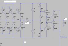
Here is what I have come up with as a VAS clamp for one of my current designs, which has a current feedback output stage configured with a voltage gain of 5.
The circuit tracks the supply rails for the power output devices and prevents the VAS collector voltage (of the front-end) from overdriving the CFB OPS.
The circuit is pretty self explanatory; the 4k and 1k resistors are proportioned to give a /5 ratio (which is equal to the voltage gain of the OPS).
The collectors of the clamp transistors (which are returned to ground via the 100R resistor) can be utilised in a clipping indicator circuit, or the 100R resistor can be removed to use the circuit as a nfb clamp.
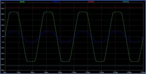
The waveform diagram shows the end result. The green trace is the output voltage, the blue trace is the VAS collector voltage (of the front-end / which is the CFB OPS input voltage) and the red and cyan traces are the output transistor rail voltages.
Reviving the previous discussion on VAS clipping and nfb clamps.
Here is what I have come up with as a VAS clamp for one of my current designs, which has a current feedback output stage configured with a voltage gain of 5.
The circuit tracks the supply rails for the power output devices and prevents the VAS collector voltage (of the front-end) from overdriving the CFB OPS.
The circuit is pretty self explanatory; the 4k and 1k resistors are proportioned to give a /5 ratio (which is equal to the voltage gain of the OPS).
The collectors of the clamp transistors (which are returned to ground via the 100R resistor) can be utilised in a clipping indicator circuit, or the 100R resistor can be removed to use the circuit as a nfb clamp.
The waveform diagram shows the end result. The green trace is the output voltage, the blue trace is the VAS collector voltage (of the front-end / which is the CFB OPS input voltage) and the red and cyan traces are the output transistor rail voltages.
Attachments
Last edited:
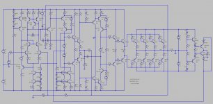
Oh, and here is the complete amp (minus supply rail filtering / OPS over current protection) just to show the complete topology.
Attachments
Last edited:
^^^ HaHa, Anatoly
-------:------
I watched the video, but have to say it doesn't contain anything spectacular... all the things mentioned should already be known by any serious designer today (note my avoidance of the term "professional"😉)
But this dScope system really is excellent in its capabilities and handling.
- Klaus
I agree. I watched it live, with on-line Q&A and such. But I was rather underwhelmed by the contents. In the announcement they gave the impression that they would discuss a new type of testing that correlates better with listening, but it was, as we Dutch say, old wine in new bags. Just a dScope plug.
jd
Last edited:
Oh, and here is the complete amp (minus supply rail filtering / OPS over current protection) just to show the complete topology.
Hi Glen,
Very interesting! Thanks for posting it. I've got a couple of questions.
1) I think one of your earlier posts showed the Miller comp of the output stage having two capacitors, each one going to an emitter of its corresponding transistor in the CFB arrangement (can't see the reference designators). Now you've got a single one going to the junction of the resistors that connect the emitters. Were you just trying to reduce parts count, or was there something more subtle going on there?
2) The global compensation is interesting - looks like some combination of TPC and TMC? Given that the output stage has gain, I guess there's some "magic ratio" of the resistors in this network?
Thanks.
I have always been a big fan of bi-amping and tri-amping for a multitude of reasons, including the good one you point out.
I started my love of audio in the tube days in the Sixties. Tube amps had their limitations. I was tri-amping with three home-built stereo amplifiers when I was in high school.
Another reason I tri-amped was that I did not like winding crossover inductors! For me, active crossovers were simpler, although I must admit unsophisticated at the time.
Each of my Athena active loudspeakers has four 125-watt MOSFET power amplifiers built into it, with a 3-1/2 way active crossover. People may think I'm crazy putting a 125-watt amplifier behind a tweeter, but I've seen 30-volt peaks across the tweeter on some material (yes, my favorite crest-factor buster, Rickie Lee Jones, Getto of my Mind).
Cheers,
Bob
In one of his papers on his site, Leach is making an interesting observation.
If you excite an high pass filter ( gain one ) with a square wave ( bipolar +V -V) and have the fundamental repetition frequency of the square wave decreasing to be lower than the crossover of the highpass filter, a transient appears at the switching time with twice the value of V ( 6db).
If the efficiency of the tweeter is the same as the woofer/medium, a tweeter power amplifier with 4 times the power of the wo/medium !!! is required to keep a balance in spl.
Square wave is irrealistic but gives an hint on the influence of wide band music on high pass filters in a transient way.
JPV
magic ratio?
Hi Andy,
As usual the component values are unintelligible, but IF these two resistors have the same ratio as the ones that define the gain of the OPS (1:4) then it's simply TMC.
Regards,
Edmond.
PS: See also R18 and R19 of the PMP amp.
Hi Glen,
[snip]
2) The global compensation is interesting - looks like some combination of TPC and TMC? Given that the output stage has gain, I guess there's some "magic ratio" of the resistors in this network?
Thanks.
Hi Andy,
As usual the component values are unintelligible, but IF these two resistors have the same ratio as the ones that define the gain of the OPS (1:4) then it's simply TMC.
Regards,
Edmond.
PS: See also R18 and R19 of the PMP amp.
...but IF these two resistors have the same ratio as the ones that define the gain of the OPS (1:4) then it's simply TMC.
That's what I was thinking, but I got a bit confused because Glen mentioned over in the YAP thread that he was using TPC 🙂.
Hi Glen,
Very interesting! Thanks for posting it. I've got a couple of questions.
1) I think one of your earlier posts showed the Miller comp of the output stage having two capacitors, each one going to an emitter of its corresponding transistor in the CFB arrangement (can't see the reference designators). Now you've got a single one going to the junction of the resistors that connect the emitters. Were you just trying to reduce parts count, or was there something more subtle going on there?
2) The global compensation is interesting - looks like some combination of TPC and TMC? Given that the output stage has gain, I guess there's some "magic ratio" of the resistors in this network?
Thanks.
Hi Andy.
I just posted that overall schematic to give an idea of the topology. I have not fully build and tested the whole thing yet. I only really wanted to show the "brute force" (non-nfb) VAS clamp here.
1) I've found the single compensation cap in the CFB OPS to work just as well as too caps, so I went with the simpler one. The OPS has a really good transient response (see attached pic).
2) I am using TPC in this amp; that global compensation network was just a TMC experiment (the TMC feedback resistance just takes the form of a 1/5 voltage divider to compensate for the gain the the CFB OPS. I'm doing the OPS PCB with privision for TMC or TPC in the CFB OPS as well; this isn't shown in that simplified schematic either.
I should also mention that that waveform diagram I posted (of the clamp operation) was just the CFB OPS alone (driven with a voltage source with a 500R series resistor. The complete amp has about 800ns of sticking when clipping.
Cheers,
Glen
Attachments

Last edited:
- Home
- Amplifiers
- Solid State
- Bob Cordell Interview: Negative Feedback