andy_c said:Sorry, but Cherry is every bit as much of a fraud as Otala was.
Come on Andy, Cherry is a good guy (opposed to Otala).
I know that some people were unsuccessful to build Cherry's amps. But don't blame Cherry, rather the poor guys who ignored his further recommendations. Cherry and a couple of others has built tens of his amp and they do work, thus no fraud at all.
Cheers, Edmond.
Edmond Stuart said:
Hi JCX,
I agree with you, but NDFL is NOT the same as 'including the OPS into the Miller loop'
Cheers, Edmond.
look closer, my smplCherryMosfetAmp sim is from the Cherry paper - C1 and C6, C10 could be counted but wasn't "added" to the basic amp
".. The present report describes how two NDFLs can be added to a familiar basic power amplifier topology..."
jcx said:look closer, my smplCherryMosfetAmp sim is from the Cherry paper - C1, and C6, C10 could be counted but wasn't "added" to the basic amp
".. The present report describes how two NDFLs can be added to a familiar basic power amplifier topology..."
Hi JCX,
It was just a remark to avoid confusion. You are talking about NDFL plus "including the OPS.......", and I was talking (in first instance) about the latter without NDFL. As Cherry's paper isn't particular clear about this matter, I like to point out that we have to deal here with two completely different issues. That's all.
Cheers, Edmond.
Jcx, you do not solve stability of real implementation in your assumptions (high NFB design with ultralow distortion through whole audioband).
Build high NFB and compare to HEC or Bob's at 10kHz spectrum. I will be very interested in results of such comparison, but not so much in simulated results of simplified reality.
Build high NFB and compare to HEC or Bob's at 10kHz spectrum. I will be very interested in results of such comparison, but not so much in simulated results of simplified reality.
PMA wrote:

Which papers are you refering to? I just read the IIM one, the one that says it doesn't matter to IM how you generate the closed loop o/p Z.Why Otala - it was explained several times by Bob, useless to repeat. Though Otala belongs to those whose work hit only a temporary technology problem, Bob Cordell's papers have universal validity.
I don't think you need it.Pete B wrote: Where is the ignore feature on this forum?

jcx said:models used in CordellMosfetAmp and smplCherryMosfetAmp sims
http://www.diyaudio.com/forums/showthread.php?s=&postid=1072546&highlight=#post1072546
http://www.diyaudio.com/forums/showthread.php?postid=1324657#post1324657
attached - open with notepad to avoid linebreaks in "smarter" editors
Oops - added 2n5501 some people may need to reload
jcx,
How do we think these models compare to the MOSFET models that Andy_C and edmond have been working on (I realize they were focusing on the Toshibas, but I think the issue is the same
Thanks,
Bob
Re: Re: Re: Re: Re: Real World Implementations
😀
Cheers, Edmond.
Actually I've tried both the TMC and a dual pole version, with essentially the same (good) results. Perhaps the differences are below the resolution of my equipment (Amber 5500)?
[sip]
Thanks,
syn08
😀
Cheers, Edmond.
I'm in favor of using the best available models, however I thought the 150 mA bias was above the "sub threshold" exponential gm region that was poorly modeled - and the speculation was better subthreshold modeling would likely make the AB Mosfet ouptut more linear in the "gm doubling" region
in any event the my point is the comparison of feedback error correction vs high gain negative feedback using the same output device (models) and bias, the smplCherryMosfetAmp sim needs more tuning to be a fair comparison but points in the direction that "pure" negative feedback is easily capable of the same performance as the feedback EC shown in my CordellMosfetAmp sim - to further nail down the point that the two are fundamentally equivalent in "desensitivity" as evidenced by distortion reduction performance
in any event the my point is the comparison of feedback error correction vs high gain negative feedback using the same output device (models) and bias, the smplCherryMosfetAmp sim needs more tuning to be a fair comparison but points in the direction that "pure" negative feedback is easily capable of the same performance as the feedback EC shown in my CordellMosfetAmp sim - to further nail down the point that the two are fundamentally equivalent in "desensitivity" as evidenced by distortion reduction performance
jcx said:in any event the my point is the comparison of feedback error correction vs high gain negative feedback using the same output device (models) and bias, the smplCherryMosfetAmp sim needs more tuning to be a fair comparison but points in the direction that "pure" negative feedback is easily capable of the same performance as the feedback EC shown in my CordellMosfetAmp sim - to further nail down the point that the two are fundamentally equivalent in "desensitivity" as evidenced by distortion reduction performance
not equivalent, nfb without ec is superior see this link www.nfbsims.de/nfbvsec.php
diy2000 said:
diy2000,
I get a blank sheet if I click the link. Anything wrong?
Jan Didden
HEC, TMC and NDFL
Gentlemen,
I have very high respect for all of you. Of course we have all been guilty of some squabbling along the way. I think we are on a good track here, and let's pursue it further to move the ball forward on our mutual understanding of distortion-reducing techniques.
Although I have had good results from HEC, I like the idea of trying to come up with reasonable apples-apples comparisons among them, and let the best technique win. I guess I started some of this recent discussion by saying that I was unaware of non-HEC techniques that did as well in the real world. I'm glad it got a response.
I have not been able to participate quite as much lately due to illness of my wife, but let me encourage all of you to pursue this comparison further, everyone showing good will and mutual respect, searching out the truth, wherever it will lead. I will be the first to admit that I do not have a lot of experience with TMC and NDFL, so I really look forward to this. I also understand the difficulty in coming up with fair comparisons that all agree are appropriate and fair.
I think it is especially a challenge to evaluate the different techniques in the context of equal stability margin.
Finally, let's not get too hung up on transistor count of the different techniques, at least insofar as cheap small-signal transistors. Plus or minus a couple of such transistors here and there is not a big deal. For ease of comparison, we may also want to compare these techniques with circuits that are fully discrete as well (although I realize that some may object to leaving op-amp-based solutions out of the comparison for now).
Since high-frequency distortion performance is the most difficult to achieve, I suggest that the comparisons be based on either THD-20 or CCIF, rather than THD-1.
Cheers,
Bob
I hope your family situation works out well Bob
I rolled together an "improved" version of my smplCherryMosfetAmp sim and my CordellMosfetAmp sim
I've plotted "loop gain" as measured by the tain/middlebrook methods - see your swcadiii/examples/educational/loopgain2.asc
also I show the simple series Vsource and full "loop gain" curves for the Cordell EC amp because there is an interesting difference that needs explaining - but I don't have the explaination yet - and the simple method gives a curve that meets my understanding of what the EC circuit is doing to output stage distortion
both methods agree at the gain intercept so I'm pretty confident that the stability is properly represented by these curves
Green is smplCherry NDFL sim, left circuit
Red/Yellow my CordellMosfetAmp sim with 2 "loop gain" mesurement methods
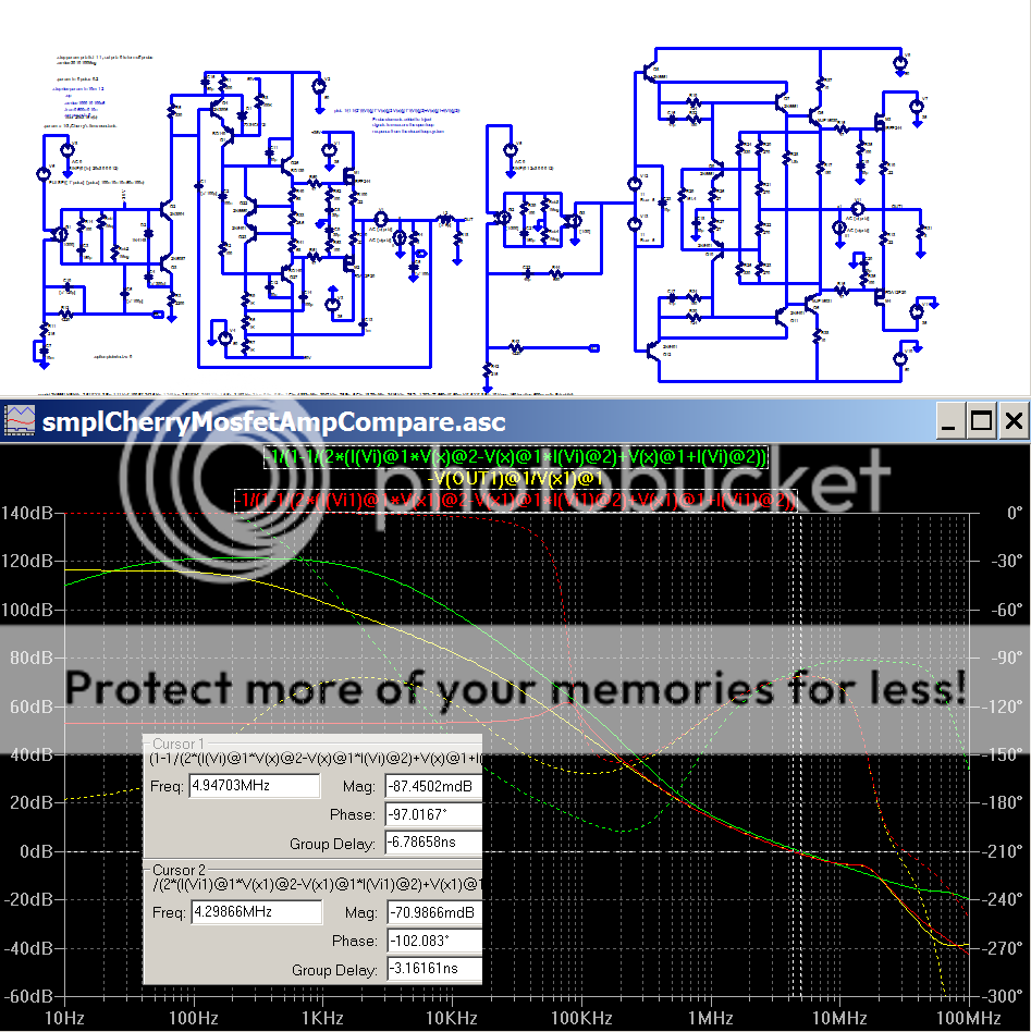
cursor 1: smplCherry gain intercept
cursor 2: Cordell EC gin intercept
The smplCherry NDFL is quite similar in high frequency stability to my Cordell EC sim - but the Cherry loop gain increases more aggressively at lower frequencies than the Cordell amp sim, indicating a greater propensity for Large signal instability/bad clipping performance as a trade for greater gain at high audio frequencies that brings down Bob's thd20
I claim the similar distortion reduction results are directly related to the gain around the output Mosfets
I presently suspect the minor positive feedback loop inherent in the EC scheme of complicating the Tain loop gain calculation, I'm currently looking for a clear explaination of measuring T and calculating desensitivity with (unstable) minor loops inside stable negative feedback amplifiers - any pointers?
I rolled together an "improved" version of my smplCherryMosfetAmp sim and my CordellMosfetAmp sim
I've plotted "loop gain" as measured by the tain/middlebrook methods - see your swcadiii/examples/educational/loopgain2.asc
also I show the simple series Vsource and full "loop gain" curves for the Cordell EC amp because there is an interesting difference that needs explaining - but I don't have the explaination yet - and the simple method gives a curve that meets my understanding of what the EC circuit is doing to output stage distortion
both methods agree at the gain intercept so I'm pretty confident that the stability is properly represented by these curves
Green is smplCherry NDFL sim, left circuit
Red/Yellow my CordellMosfetAmp sim with 2 "loop gain" mesurement methods
cursor 1: smplCherry gain intercept
cursor 2: Cordell EC gin intercept
The smplCherry NDFL is quite similar in high frequency stability to my Cordell EC sim - but the Cherry loop gain increases more aggressively at lower frequencies than the Cordell amp sim, indicating a greater propensity for Large signal instability/bad clipping performance as a trade for greater gain at high audio frequencies that brings down Bob's thd20
I claim the similar distortion reduction results are directly related to the gain around the output Mosfets
I presently suspect the minor positive feedback loop inherent in the EC scheme of complicating the Tain loop gain calculation, I'm currently looking for a clear explaination of measuring T and calculating desensitivity with (unstable) minor loops inside stable negative feedback amplifiers - any pointers?
Bob, hope your wife gets well soon.
Jcx,
I think your Cordell circuit is a tad "over-nulled". If I am interpreting the graph properly the phase margin is pants and the red curve is showing a resonance at 80kHz. Bob's circuit should have about 90 deg of phase margin into an 8-ohm resistor when the loop gain is 30dB at 20kHz, as it is in the real circuit. I make the unity loop gain frequency about 3MHz.
The Cherry graph looks grossly unstable to me.
Attached is my Cordell circuit with the FFT for 20kHz 28.3V amplitude sinewave (50W average into 8 ohms). I used a 10ms period and 10ns step size for the transient analysis, all compressions disabled.
My simulation shows a very good -86dB H2 and -81dB H3.
Attachments
Jcx,
I misunderstood your Cordell graph. You are measuring the whole amplifier, not just the output stage. My graph and such are just for the output stage so they cannot be compared directly.
Brian
I misunderstood your Cordell graph. You are measuring the whole amplifier, not just the output stage. My graph and such are just for the output stage so they cannot be compared directly.
Brian
yes I am trying for "whole amp" gain around the output stage, the Small signal stability is very similar with 83 vs 78 degree phase margin at the 0dB gain intercept, the smplCherry sim actually looks more stable at higher freq as measured by high frequency gain margin - where the phase shift reaches 180 degrees
the smplCherry sim is however conditionally stable and has a "lower gain margin" of ~ 20 dB @~500 KHz, the >180 phase shift at ~100 KHz means clipping could induce Large signal oscillations - if the system was overdriven to the point of 20 dB "gain reduction" in the describing function sense
If the anticipated large signal instability can be overcome by small handfull of extra components then this Cherry NDFL approach and conditionally stable loop gains in general could still be usable - and a bargain with respect to distortion reduction at audio frequencies with limited power stage bandwidth
B.J. Lurie makes a strong case for the usability of conditionally stable gain in practical control systems:
http://www.luriecontrol.com/FeedbackMaximization.htm
jcx,
I'm surprised you are getting that dip in the Cherry gloabl loop gain...when I ran your model the other day, having first replaced the input circuitry with just a current source driving the miller stage (because I was just interested in the OS performance), the loop gain was pretty normal. I wonder what is causing the dip.
The whole subject of control system design interests me. I have not done any homework on conditionally stable systems...I have always focussed on making the loops as stable as possible in audio amplifiers. Off the top of my head I would guess that adding some PFB mid-band will improve the responsiveness of the system at certain frequencies but probably do so at the expense of increasing distortion at those frequencies. Just a guess...I haven't done the maths.
Brian
no "gain dip" - in the LtSpice plot the solid green is the |gain|, which is monotonic decreasing above audio
the dotted green line is phase, which does show the phase response dips below 180 degrees in the ~ 100 KHz region - while the gain is high (>20 dB)
the dotted green line is phase, which does show the phase response dips below 180 degrees in the ~ 100 KHz region - while the gain is high (>20 dB)
Hi Jcx,
First, I'm glad that you too will break a lance for Cherry. This man deserves far more recognition than he gets from those AH's on this forum who obviously don't understand him or even accusing him of fraud.
Having said this, let's come to the point. Using Bob's words "trying to come up with reasonable apples-apples comparisons among them, and let the best technique win". In other words, we must make a fair comparison between HEC and NFB topologies.
In Cherry's example (smplCherry) there are two methods applied to reduce distortion:
1. A nested differentiating feedback loop (NDFL)
2. The inclusion of the output stage into the Miller compensating loop.
BTW, let's define an acronym for his 2nd trick: "OMC" (everybody okay?)
As each of these two methods can reduce the THD20 maximally by about 20dB, it's not 'fair' to compare his circuit with HEC. However, as several stages of Cherry's amp are less sophisticated than in Bob's amp, this lead in advantage will not fully exploited.
Anyhow, to make a fair comparison, one should only apply one of both of these techniques and compare the performance of such an amp with HEC.
Cheers, Edmond.
Edmond Stuart said:First, I'm glad that you too will break a lance for Cherry. This man deserves far more recognition than he gets from those AH's on this forum who obviously don't understand him or even accusing him of fraud.
Yes. I've communicated with him and found him to be pretty
modest about his work. You might find it flawed, but it is
certainly worth reading.
😎
- Home
- Amplifiers
- Solid State
- Bob Cordell Interview: Error Correction