traderbam said:I've shown the proof that Hec depends on infinite gain. You prove me wrong! Show me your mathmatical proof. [snip]
I did. The equations I referred to (global fb vs H.ec) show that they are fundamentally different. One can never null even in theory, the other can easily null in theory.
traderbam said:[snip]I'd like to drop this debate and continue to analyze Bob's output stage and see if there are opportunities to improve it. [snip]
OK.
Jan Didden
Oops, sorry PB2. I omitted the "/" by mistake. I'm happy for my post #882 to be deleted completely.
Andy C wrote:
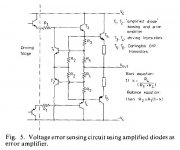
There are three inputs to the "S1" summer, PFB from the gate driver via the 330 ohm resistors, NFB from the output via 270 ohms and NFB from the gate driver. The latter is not in Hawksford's original model although I see it is in his fig 5. I also notice that Bob has not implemented fig 5 because Hawksford has the collector of T2 going to the psu rail. What do you make of that?Not sure which NFB path you're referring to.
Attachments
Jan wrote:
Jan, would you show me your EC system that can easily null the error out of my non-linear gain device, A, where A(x) = x^2?I did. The equations I referred to (global fb vs H.ec) show that they are fundamentally different. One can never null even in theory, the other can easily null in theory.
traderbam said:Jan wrote:Jan, would you show me your EC system that can easily null the error out of my non-linear gain device, A, where A(x) = x^2?
Brian,
Several people including me have discussed and shown the H.ec that can null the forward gain A from the cl equation. In theory, of course. Whatever A is. The only requirement (for the math) was that A is not equal to zero. Mikeks has shown several topologies. I have no ambition to repeat all that one more time.
Jan Didden
traderbam said:🙄 You can lead a horse to water but you can't make it drink.
Neither can you force people to their happiness! 😀
Jan Didden
Final contribution
Gentlemen,
I should like to wrap up my involvement for the time being with a summary.
Error correction represents an error reducing design strategy different from conventional negative feedback. This holds no matter the fact actual realization happens to translate into equivalent formal gain expresions.
I want to emphasize the "design strategy" concept, for by topology, the objective is to null error by comparing plant input and output.
- Implicitely, as a consequence of implementation with real elements the correction factor increases with decreasing frequency reaching a theoretical infinite at DC.
Interestingly, negative feedback systems with extremely high open loop gain usually insert a very low frequency dominant pole, yielding a similar correction/attenuation performance.
- Stability is an issue but then it is also an issue in conventional negative feedback systems where open loop gain is very high.
- Implementation is straightforward with the current generation of available devices.
Rodolfo
Continuing from here, it is clear that, conrary to Ingrast, figures 1 and 2 here are equivalent, since this balance equation reduces to Vo/Vi=K, as expected at balance.
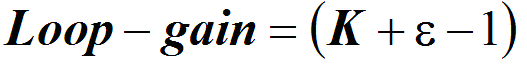
Moreover, it is also apparent that system loop transmission, given an output stage with an arbitrary nominal gain K, is given by:
Moreover, it is also apparent that system loop transmission, given an output stage with an arbitrary nominal gain K, is given by:
Attachments
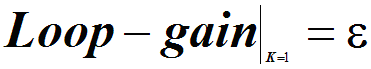
Therefore, in respect of an output stage where it is desired that K=1, contrary to my previous submission, it follows from the above expression that:
Attachments
In Conclusion:
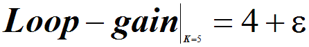
Given that the above expressions demonstrate that only a modest loop gain is required at balance, i am at loss to understand why some consider that infinite negative feedback (viz. loop gain) is mandatory for 100% error cancellation by negative feedback.
Given that the above expressions demonstrate that only a modest loop gain is required at balance, i am at loss to understand why some consider that infinite negative feedback (viz. loop gain) is mandatory for 100% error cancellation by negative feedback.
I can’t tell if jann and Rodolfo are giving up too soon on trying to understand this feedback fundamental – Rodolfo’s statement seems to still draw a distinction that simply doesn’t exist, the various topologies put forward may result in different implementations depending on the mapping of arithmetic to hardware but they are all equivalent to linear feedback systems with command feedforward, 2-degree of freedom feedback systems with the same stability limits and distortion reducing potential when implemented with similar gain-bandwidth devices – not an interesting coincidence, but a fundamental equivalence
The Cordell and “1st Hawksford” “error correction” are equivalent to 2-degree of freedom feedback systems, see p12-13 of http://www.control.lth.se/~kja/modeluncertainty.pdf,
You can rearrange the blocks and arithmetic but if you are operating linearly on a reference input and a measurement of output error from a single input, single output “plant” (output stage power transistor pair in our example) then you can at best have a 2 degree system (error + feedforward)
Horrowitz “Feedback System Synthesis”, 1963 gives a page full of 2-degree feedback system diagrams and shows they are all equivalent (the ref 24 referred to in the above pdf), most of the diagrams here have been variants of "model reference" or "conditional feedback" control in Horrowitz' classification
Some of the latter Hawksford “generalized error correction” papers introduce a term summed with the output – that output power summer is The distinguishing system feature that changes capabilities of the system from a simple feedback system
mikeks said:Therefore, in respect of an output stage where it is desired that K=1, contrary to my previous submission, it follows from the above expression that: {loop_gain=epsilon in graphic}
Hey, I like that result. Clearly it could lead to some observations about how to get the best loop stability - like avoiding peaking in the frequency response of the output stage.
I think the high loop gain that traderbam is referring to is in the outer loop where the probe is placed just in front of the diff amp (in the path containing the output stage).
Hi Mike. That paper you posted on topological equivalences by Texas Instruments was great.
I would caution you to be careful because this rearrangement method only works with linear blocks. It does not work with non-linear elements as addition and subtraction do not work. So if your non-linear block is represented by K1 and S1, S2, K2 and K3 are all linear, you should leave K1 alone and manipulate everything else around it.
If you do this you should find the loop gain of your fig 1 is -K1.K2.K3/(1 - K2.K3)
Loop gain goes infinite when K2.K3=1 as expected.
Yes Andy, I am always talking about the loop gain of the loop that includes the output device - the device the system is trying to "correct".
Brian
Brian
jcx said:[snip]the various topologies put forward may result in different implementations depending on the mapping of arithmetic to hardware but they are all equivalent to linear feedback systems with command feedforward, 2-degree of freedom feedback systems with the same stability limits and distortion reducing potential when implemented with similar gain-bandwidth devices[snip]
Well, that is where I have my problem in understanding this. On the one hand, we have a system where the distortion reduction cannot ever be complete - the best that can be done is, with infinite loop gain - to assymptotically get closer and closer to zero but never getting there.
On the other hand we have a system that - with the simple tuning of a passive voltage divider - can actually reduce distortion to zero and even go beyond this null and make the distortion re-appear in opposite phase.
I fail to see why these two systems would be fundamentally the same - I would say they are fundamentally different.
BTW jcx your link appears broken?
Jan Didden
traderbam said:I would caution you to be careful because this rearrangement method only works with linear blocks.
I know this.
traderbam said:It does not work with non-linear elements as addition and subtraction do not work.
Where are these ''non-linear'' blocks?

traderbam said:
So if your non-linear block is represented by K1 and S1, S2, K2 and K3 are all linear, you should leave K1 alone and manipulate everything else around it. If you do this you should find the loop gain of your fig 1 is -K1.K2.K3/(1 - K2.K3) Loop gain goes infinite when K2.K3=1 as expected.
This is wrong. I am really fatigued by all this, so finding out why you are wrong is your homework.

Hint: K1 is error + ideal output stage gain.
janneman said:BTW jcx your link appears broken?
Hi Jan,
Just edit out the punctuation mark after the ".pdf" in the URL.
On another subject, I think the ongoing controversy isn't much of a controversy at all when all is said and done. Rather, I see it as different people having different ways of looking at the same problem. One person's concept is another person's implementation detail and vice versa. Regardless of whether error correction is a concept in itself or just a particular implementation of a general feedback system, the "con-plementation" is an incredibly useful one.
- Home
- Amplifiers
- Solid State
- Bob Cordell Interview: Error Correction