It's a terrible pity that all the serious engineers have either been forced out of this site or have left voluntarily....eg Andy_c...Gk....etc
The guy is just trying to rile up people rather than to contribute to and advance a community.
You have nailed it.
From Wikipedia, in Internet slang, a troll is someone who posts inflammatory, extraneous, or off-topic messages in an online community, such as an online discussion forum, chat room, or blog, with the primary intent of provoking readers into an emotional response or of otherwise disrupting normal on-topic discussion. The noun troll may refer to the provocative message itself, as in: "That was an excellent troll you posted".
Cheers,
Bob
Gentlemen,
Whatever.
Probably because I do not know enough, the issue of spice based simulation accuracy as regards quantitative prediction of higher order phenomena like various types of distortion at the ppm level is not settled. I tend to take seriously results form people here that deserve credibility as per their posting history, but sure it is not enough.
As suggested in an earlier post, I am not particularly motivated neither have time and frankly am not sure if qualified enough to research this topic, but will analyze results from others with interest.
I believe this is no minor issue.
Constructing and measuring performance at this level is tricky, expensive and beyond reach for most of us.
If it can be proved beyond doubt that simulation is up to the task of predicting ppm levels of distortion, provided a well designed protocol for configuration, model qualification etc. is followed, then this is a major change of paradigm on what high performance audio respects.
Rodolfo
the issue of spice based simulation accuracy as regards quantitative prediction of higher order phenomena like various types of distortion at the ppm level is not settled.
I guess poor HAFH students always have a little spare time for interesting stuff, so...
Here's a small comparison between LTSPICE and our standard tool at the university (Cadence PSPICE).
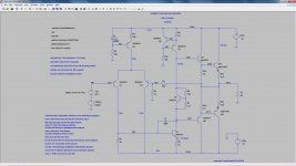
I downloaded the LTSPICE tutorial simulation package from Bob Cordell's website CordellAudio.com - Tutorial Simulations I've
chosed to look at the fig. 19.7 simulation as being the closest to a rel world implementation. 19.7 is not something that I would implement in the
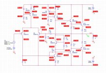
real world, it's lacking to many features (to name a few, input stage degeneration, beta enhancer, proper output stage bias) but for the purpose of this work is ok. The LTSPICE schematic, captured from the computer screen, is attached.
I haven't touched anything in Bob's schematic or simulation settings, so anybody can reproduce the results, by simply loading the .asc file and
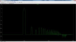
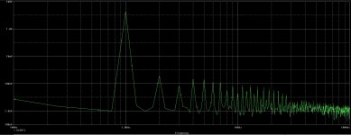
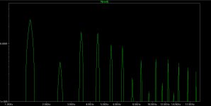
running the sim. For an apple to apple comparison, I had though to adjust a little the FFT output display. Y axis is now logarithmic in volts, 1E-7V
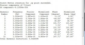
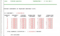
to 100V, while the X axis is 100Hz to 100KHz, also logarithmic. The LTSPICE output spectrum is attached, and so are the THD @ 1KHz results. THD @1KHz is 0.002655%.
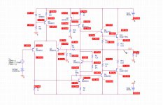
The next step was to port the exactly same schematic and settings in PSPICE. I had to re-capture the schematic (an easy job, I also kept the same component labels, for an easy follow up. I created a special model library with the Cordell models (BTW, some of those models are still very crude) and used it in the PSPICE sim. I also used exactly the same number of periods (for the sake of the FFT analysis), the same transient step, etc... as in the LTSPICE sim. If somebody want to double check these, I can forward the PSPICE files. The PSPICE schematic, captured from the computer screen, is attached. It also shows the bias simulation results. As everybody can see, the bias results are very close to those in LTSPICE: 109.1mA vs. 110mA bias current in the output stage. This confirms that the schematic was correctly captured and the Cordell device models are correctly used in this PSPICE exercise.
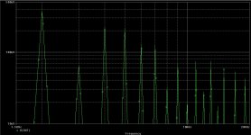
Now, on to the attached PSPICE output FFT spectrum results. It is plotted in exactly the same coordinates and limits as the LTSPICE spectrum, for an easy comparison. The results seem to be quite different; while in LTSPICE the second harmonic is higher than the third (which, given the circuit topology, is a suspect result by itself) in PSPICE the output FFT spectrum looks more balanced/monotonic. Again based on the circuit toplogy I would trust the PSPICE results, but who's better is beyond the purpose of this work.
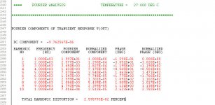
The THD @1KHz results in PSPICE are also attached. THD @1KHz is 0.0136%, or about 5 times larger than in LTSPICE, and we are far away from the ppm level fine details. A closer inspection shows that the spectral components amplitude can't explain the big discrepancy; it's also the phase of the components that is totally different. Again based on
the (poor) circuit topology I would trust PSPICE here, the 0.002655% from LTSPICE looks to me awfully optimistic.
I hope this clarifies how much can be raw THD simulations trusted. This is not to say that simulation tools are not good; they are excellent tools,
if used properly. Using properly doesn't only include proper and validated device models. It also includes careful numerical parametric calibration against measurements and many other such things that are well beyond the DIY space. Universities and large corporations are investing millions in
calibrating simulators, and a calibration set is usually valid only for a small subset of applications or technology.
For DIY purposes, I don't think relying on simulated absolute THD values makes any practical sense. For a given circuit topology, a simulation tool is though good for incrementally comparing results. E.g. for answering questions like "what's happening with the THD @1KHz if I increase Cdom"?
Attachments

I guess poor HAFH students always have a little spare time for interesting stuff, so...
Here's a small comparison between LTSPICE and our standard tool at the university (Cadence PSPICE).
I did a rather stupid error in the above post; the feedback resistor in the PSPICE should be 19k, rather than 10k, for a gain of 20.
But this only makes the THD @ 1KHz simulation gap worse; see the attachments. The spectral components in PSPICE are now much larger while the spectral component phases are still widely different. The only thing that seems to be "fixed" is the aspect of the spectrum; now in both cases the 2nd harmonic is larger than the 3rd.
Attachments
what is the PSpice transient setting?, lots of other options control integration accuracy too - but at least in Ltspice I find smaller time steps usually gives converging results
try cutting max time step by 4-10x, see if you get the same results, keep refining Pspice sim settings until the simulated distortion quits changing
there are also differing levels of models for transistors used in different sims, even then reading the Ltspice changelog will show that Mike has had to debug the model code for various parameters
I wouldn't argue for absolute accuracy of sim vs real parts but 2 different spice simulator implementations, based on the same Berkley Spice definitions should be able to be set up to converge on "the same" results if you are well above numerical error levels and the models agree
perhaps it is the case that different simulator's transistor models have been debugged to different levels of compliance
another test would be to use simpler behavioral sources to give calculable distortions - at least that would allow checking sim integration, tolerance options effects
I don't think calculating the time step size based on fft resolution is useful - the spice engine will often have to take smaller steps, not be aligned with the sampling used in the waveform fft processing - I use an "even" max time setting at least 2x finer than the implied sampling for the fft - or several times faster than the device ft if I'm really interested in stability - millions of point sims aren't really a problem with todays PCs
Last edited:
If I'm not mistaken, the first few harmonics are about -90..-100 dB down in both SPICEs when looking at the FFTs - so they would seem to be agreeing reasonably well. .FOUR results in LTspice are overly optimistic for some reason, hence I don't use this function any more (it's plenty fussy anyway).
In the LTspice group I just ran across this Audio Analyser. Looks interesting at least, no idea how well it works yet..
In the LTspice group I just ran across this Audio Analyser. Looks interesting at least, no idea how well it works yet..
Last edited:
try cutting max time step by 4-10x, see if you get the same results, keep refining Pspice sim settings until the simulated distortion quits changing
there are also differing levels of models for transistors used in different sims, even then reading the Ltspice changelog will show that Mike has had to debug the model code for various parameters
I'm not debating if the results can be made consistent - they can certainly made so, by adjusting the sim parameters as you mentioned (BTW, lots of such params in PSPICE as well). The question is: how much can we trust absolute THD results when simulators are not even close to agree, at least by default? And then again, we are here dealing with the 0.01% distortions levels, not 0.0001%. Yes, the model templates and (default) levels could be different from simulator to simulator, in fact they usually are, so even the same model files can give different sim results. Another thing that has to be carefully (cross)checked before blindly trusting the simulation results.
If I'm not mistaken, the first few harmonics are about -90..-100 dB down in both SPICEs when looking at the FFTs - so they would seem to be agreeing reasonably well.
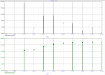
They don't. PSPICE spectral components are significantly larger in amplitude compared with the LTSPICE results. And component phases are dramatically different. Check the attachments, I zoomed the spectra, while keeping the same scales. I don't know how to add grid lines in LTSPICE, but the differences in amplitude are obvious.
Attachments
Last edited:
Walter, your sim with Cadence PSPICE is crappy.
With MicroCap I got almost the same spectra as with LTSpice (within say 1%).
Calibrate and/or check that Cadence thingy with a well defined signal, for example a 1kHz sine of 1V and superimposed with 3kHz and 10uV.
With MicroCap I got almost the same spectra as with LTSpice (within say 1%).
Calibrate and/or check that Cadence thingy with a well defined signal, for example a 1kHz sine of 1V and superimposed with 3kHz and 10uV.
THD of input signal
Hello Walter
What is the THD of the input signal of the (Pspice) simulation .
Hello Walter
What is the THD of the input signal of the (Pspice) simulation .
using defaults isn't "fair" if they give poor results compared to another sims defaults
that would be something Marketing would try to diss the competion - not how Engineers compare tools
there's no point in comparing results when one tool is being used at much lower resolution/accuracy than the other
the only "ineresting" result is when and why different simulators givwe differnt result running at their most accurate levels
Last edited:
What is the THD of the input signal of the (Pspice) simulation .
Good question, see below.
Attachments

Walter, your sim with Cadence PSPICE is crappy. With MicroCap I got almost the same spectra as with LTSpice (within say 1%).
Maybe, but instead of a blank statement why don't you take Mr. Cordell's advice and post your MicroSim results so everybody could do their own evaluation?
Otherwise, if you believe the Fig. 17.9 topology in Mr. Cordell's book can do 25ppm THD @1KHz, as prompted by both LTSPICE and (according to your results) MicroSim, that's your choice and I won't debate that.
refusing to take simple steps to see if your sim is accurate is not too defensible
does the distortion in your sim change with much smaller max time step?
if it does then how do you justify which numbers to use in a comparison with another simulator
the default setting agruement is totally bankrupt
does the distortion in your sim change with much smaller max time step?
if it does then how do you justify which numbers to use in a comparison with another simulator
the default setting agruement is totally bankrupt
default settings
Hi jcx,
I'm not sure to whom you are talking, but of course I've varied the time step and other parameters (if that's what you mean) in order to convince myself that my simulator is not lying.
Cheers,
E.
Hi jcx,
I'm not sure to whom you are talking, but of course I've varied the time step and other parameters (if that's what you mean) in order to convince myself that my simulator is not lying.
Cheers,
E.
Maybe, but instead of a blank statement why don't you take Mr. Cordell's advice and post your MicroSim results so everybody could do their own evaluation?
Here they are. Are you satisfied now?
Otherwise, if you believe the Fig. 17.9 topology in Mr. Cordell's book can do 25ppm THD @1KHz, as prompted by both LTSPICE and (according to your results) MicroSim, that's your choice and I won't debate that.
Yes, I do believe that and if you can't handle a simulator properly, you better not debate it.
BTW, I'm NOT using MicroSim.
Code:
   F(Hz)      THD(ppm)    IHD(ppm)
   0.000K     0.000        0.000
   1.000K     0.000        0.000
   2.000K    19.010       19.010
   3.000K    19.306        3.367
   4.000K    22.292       11.145
   5.000K    24.828       10.931
   6.000K    26.752        6.577
   7.000K    26.450        6.321
   8.000K    26.502        1.647
   9.000K    26.734        3.515
  10.000K    26.752        0.976
Attachments
And you Michael lose all, if any were left, credibility for not showing us the way.I rest my case. Bob, over to you!😎
Leaving it to Waly, who is not familiar with LTspice, to do this first comparison
for us, you gain no points.
I expect better from our knowledgeable Members.
I know you can do better, but these recent post do you no favours.
Hi Andrew,
Not LTspice was erroneous, rather the Cadence sim.
For an easier comparison I've put the figures together:
Clearly the Cadence figures are subject to error.
(btw, a better optimized 'blameless' does about 10ppm THD @ 1kHz, that is, measured)
Cheers,
E.
Not LTspice was erroneous, rather the Cadence sim.
For an easier comparison I've put the figures together:
Code:
   F(Hz)   MC9-THD(ppm) MC9-IHD(ppm)  LT-IHD  Cadence-IHD
   0.000K	 0.000       0.000    -----    -----
   1.000K	 0.000       0.000    -----    -----
   2.000K	19.010      19.010    18.84    129.0
   3.000K	19.306       3.367    33.30    182.7
   4.000K	22.292      11.145    11.13     71.75
   5.000K	24.828      10.931    10.80     35.40
   6.000K	26.752       6.577     6.604    77.48
   7.000K	26.450       6.321     6.225    13.01
   8.000K	26.502       1.647     1.656    54.39
   9.000K	26.734       3.515     3.487    23.99
10.000K 26.752 0.976 0.998 35.13(btw, a better optimized 'blameless' does about 10ppm THD @ 1kHz, that is, measured)
Cheers,
E.
there's no point in comparing results when one tool is being used at much lower resolution/accuracy than the other
the only "ineresting" result is when and why different simulators givwe differnt result running at their most accurate levels
True. But i think you'll find, as i have done, that regardless of settings different simulators give wildly different results.
Just compare LTSpice with Multisim or Simetrix.
Incidentaly, Simetrix is the BEST SPICE simulator for everything else, and is used by such luminaries as Hans Camenzind. See:
http://www.designinganalogchips.com/_count/countdown.pl?designinganalogchips.pdf
Last edited:
- Home
- Amplifiers
- Solid State
- Bob Cordell Interview: Error Correction