janneman said:The old standby uPC1237 would do something like that with added flexibility.
Hey, that's a neat part. I will definitely study the datasheet - thanks!
see an indestructible amplifier
Old news, but the DartZ comes pretty close.
Hi Jacco,
-Chris
I am not familiar with that one. Maybe they never break? 😉Old news, but the DartZ comes pretty close.
-Chris
anatech said:Hi Andrew,
I think you will agree that no protection system is infallible. All you can really hope to do is limit the damage.
I have yet to see an indestructible amplifier.
-Chris
I agree. It's all about probabilities and applications. There will always be some kind of a load or screw-up that can create damage. The best we can do is to keep it down to an extremely low probability for the kind of use we foresee.
Cheers,
Bob
andy_c said:
Hi Bob,
I think this is the best idea I've seen for non-intrusive output stage protection yet. I must admit to having been baffled as to how to do this with six transistors though. Then, after searching around a bit, I ran into figure 13 on page 10 of this document. I'm ignoring the ICs here, except for the single transistor shown as being internal to the AS273. I'm thinking that if you replace ground in that figure by the output of the amp, and connect the high side of the latch to the high side of the amp's shunt regulator, then you'd have half of the six-transistor circuit you're describing. Then the other three transistors would be just a mirror-image complement of these, allowing the low side of the amp's shunt regulator to be shunted to the amp's output as well. Does that sound right?
Thanks, Andy. There are many variations on this scheme, and I think quite a few others do something like this. What you say about figure 13 is about right.
The biggest caveat is to remember that this is not an SOA protector. In other words, an amplifier built using only this scheme, which did not have enough paralleled output transistors, could conceivably be hurt by a dynamic SOA excursion. This circuit is strictly for short-circuit protection (although in some cases it might be able to be extended to something more). I generally prefer to avoid so-called SOA V-I limiter circuits all together, using enough output transistors in parallel to handle the SOA imposed on them by the worst anticipated load.
Cheers,
Bob
Mr. Cordell,
Is the current rating of a Mosfet is determined by the "Body Diode" rating? In datasheets, the current rating of a Mosfet always the same with the rating of the Body Diode.
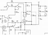
In this drawing, the internal body diode (APT50M65) is replaced by external body diode (30EPH06). Is this means the original current rating 67A (APT50M65's) is dropped to 30A (30EPH06's)?
Is the current rating of a Mosfet is determined by the "Body Diode" rating? In datasheets, the current rating of a Mosfet always the same with the rating of the Body Diode.
In this drawing, the internal body diode (APT50M65) is replaced by external body diode (30EPH06). Is this means the original current rating 67A (APT50M65's) is dropped to 30A (30EPH06's)?
Attachments
Hi Bob,
LOL!
I believe 100 % that as tough as you can make an amplifier, and as effective you can design your protection, people will figure out how to destroy the amplifier. I've seen far too many well designed amplifiers brought to their knees over my service career.
Ever see a guy complain after powering his 120 VAC amp from 550 VAC? They are all under the impression that the fuse should have gone. It's also common these days to mistake warranty with insurance. No matter what happens, it is the fault of the amplifier or manufacturer.
-Chris
LOL!
The average home user or the average part time DJ would require an indestructible amplifier.The best we can do is to keep it down to an extremely low probability for the kind of use we foresee.
I believe 100 % that as tough as you can make an amplifier, and as effective you can design your protection, people will figure out how to destroy the amplifier. I've seen far too many well designed amplifiers brought to their knees over my service career.
Ever see a guy complain after powering his 120 VAC amp from 550 VAC? They are all under the impression that the fuse should have gone. It's also common these days to mistake warranty with insurance. No matter what happens, it is the fault of the amplifier or manufacturer.
-Chris
lumanauw said:Mr. Cordell,
Is the current rating of a Mosfet is determined by the "Body Diode" rating? In datasheets, the current rating of a Mosfet always the same with the rating of the Body Diode.
In this drawing, the internal body diode (APT50M65) is replaced by external body diode (30EPH06). Is this means the original current rating 67A (APT50M65's) is dropped to 30A (30EPH06's)?
I think the body diode rating is largely coincidentally the same as the forward MOSFET current rating in most spec sheets as a reflection of the unclamped inductive load applications, such as in switching supplies. In these applications, the body diode is used as a free-wheeling diode. When the MOSFET is turned off, the inductive load will try to keep the current the same as it was when the device was on, dumping this current into the body diode under a reverse breakdown condition. Since the current immediately after turn-off cannot normally be greater than it was during turn-on, it is unnecessary for the body diode current rating to be larger than the forward MOSFET current rating. I am not an expert in this area, but this is my simple way of understanding it.
Cheers,
Bob
anatech said:Hi Bob,
LOL!
The average home user or the average part time DJ would require an indestructible amplifier.
I believe 100 % that as tough as you can make an amplifier, and as effective you can design your protection, people will figure out how to destroy the amplifier. I've seen far too many well designed amplifiers brought to their knees over my service career.
Ever see a guy complain after powering his 120 VAC amp from 550 VAC? They are all under the impression that the fuse should have gone. It's also common these days to mistake warranty with insurance. No matter what happens, it is the fault of the amplifier or manufacturer.
-Chris
Yep!
Bob
Many of you that post on this sort of thread are the "nobility" of audio. Ironically, there may be more people following here than have ever read your papers or heard your talks.
This is from post 2012. Despite the use the of the qualifier "may be" this is a strong statement. Any proof to back this up? As chief moderator can you determine the number of different people viewing the thread from the view's stat?
If there is anything substantive in this thread, at some point there has to be facts or data to support the claims made in the thread. Might as well start here as anywhere else.
Mark
Safe Operating Area Requirements
When discussing output stage protection it is important to understand the Safe Operating Area requirements placed on the output stage by non-resistive loads (e.g., loudspeakers). The safe area needed by, say, the upper group of output transistors peaks at its maximum when the product of collector-emitter voltage and positive output current peaks. The Vce is simply the rail voltage less the output voltage. For resistive loads, the output voltage and the output current are in-phase, and the peak dissipation occurs at some positive output voltage between zero and the rail voltage. Note that as output voltage and current increase, Vce actually tends to decrease, mitigating the peak power dissipation.
For reactive loads, the output voltage and output current are not in phase, and this usually makes things worse for peak power dissipation. For a typical 60-degree worst case speaker load phase angle, the point of maximum upper-half power dissipation will often occur at an output voltage that is actually negative, meaning that Vce is large at this point. This leads to unusually large peak power dissipation and helps define the maximum amount of safe area needed by the upper group of transistors.
Consider a 100-Watt, 8-ohm amplifier that is designed so that it can handle a worst-case 2-ohm resistive load or a worst-case 4-ohm, 60-degree reactive load. Note that both of these conditions might pertain to the same speaker at different frequencies. It might have its impedance minimum of two ohms at one frequency, where the phase angle will be close to zero. This might be at its tuning frequency if it is a ported design. At a slightly higher frequency, the impedance will necessarily rise, but it will take on a non-zero phase angle. It will not be uncommon for the impedance to rise to about 4 ohms when it hits 60 degrees, and this will often be close to the worst case for this speaker.
Assume that the amplifier will put out 40V peak into 8 ohms, and that its rails are fixed at 45V to allow for some output stage headroom. When feeding a 2-ohm load, the amplifier will deliver 40V peak and 20A peak into the load. The peak dissipation will occur at an output voltage of 20V and 10A, with a Vce of 25V, corresponding to a 250-Watt peak dissipation. If we only had to worry about this load, the upper group of transistors would need an SOA of 10A at 25V, which is actually not too bad. From a strictly SOA point of view, many single power output devices could handle this SOA for a brief period.
How brief, you ask? The instantaneous power dissipation of the upper group of transistors as a function of time is a fairly narrow asymmetrical pulse, since it is the product of portions of two sinusoids. The peak of the pulse is 250 watts. Let’s be conservative and say that we need to support the full SOA over the full amount of time that the power pulse is over half its peak value. Let’s also assume that the lowest frequency to be handled will be 20 Hz. It turns out that the amount of time is 9 ms (the average power dissipation during this 9 ms interval is 197 Watts). Thus, the 10 ms SOA for the upper device(s) must be at least 250 Watts (expressing SOA in terms of power is OK as long as we are below the Vce at which secondary breakdown comes into play for the transistors).
Now let’s consider the 4-ohm, 60-degree reactive load. The peak current into a 4-ohm load will be 10 Amps. The peak of the power dissipation occurs when the output voltage is -7 V and the output current is 7.7 A. Under these conditions, Vce is 52 V and peak dissipation is 400 Watts. The power pulse stays above half its peak value for 12 ms (during which time the average power dissipated in the upper transistors is 323 Watts). Thus, the 12 ms SOA for the upper devices must be at least 400 Watts. Since the average power during the interval is actually less than 400 Watts, we can probably cheat a little and use the readily-available 10 ms SOA as the number needing to be 400 Watts.
Note that the rated SOA of both the Sanken RETs and the IRFP240 MOSFETs is on the order of 300 Watts. Two pairs of devices will easily handle this SOA requirement. This is good, because in a real 100 W amplifier, the unregulated rails may rise to 55 V or so.
A convenient rule of thumb comes out of this: The required 10 ms SOA for each half of the output stage needs to be at least four times the amplifier’s maximum average power into an 8-ohm load (in other words, include dynamic headroom). Such an amplifier will then have enough SOA to drive reactive speaker loads that dip down to 2-ohms and have a 60 degree phase angle by the time they rise to 4 ohms.
There are at least two caveats here. First, the available SOA needs to be derated somewhat for the actual average device operating temperature, which will be above the 25C number where SOA is specified.
Secondly, all of this analysis has been done for sinewaves. There may be certain musical waveforms that can create larger worst-case peak power conditions, so some conservatism is in order. The key thing to watch out for is the product of peak power times how long it lasts.
Cheers,
Bob
Bob Cordell said:The biggest caveat is to remember that this is not an SOA protector. In other words, an amplifier built using only this scheme, which did not have enough paralleled output transistors, could conceivably be hurt by a dynamic SOA excursion. This circuit is strictly for short-circuit protection (...)
Hi Bob,
I guess I was thinking of your circuit in a more general way. In very general terms, you might split up how protection circuitry works into two broad categories:
1) What the protection circuit does when it kicks in
2) How the decision is made to kick it in
Unless I'm missing an important point here (and that may very well be so), the concept of separately shorting the high and low sides of the VAS shunt reg to the amp's output with discrete BJT latches looks like it could be combined with detection of when to do so based on SOA and not just current. One might envision doing this, forcing the amp's output current to zero by shorting them both at once. Then the output relay could be de-energized and the amp shut off.
Why might this be better than traditional SOA protection that doesn't shut off the amp? When traditional SOA protection activates, it tends to go into a kind of oscillation. It activates, the SOA is no longer exceeded, so it deactivates. But then the condition that activated it may just reappear again, re-activating the SOA protection again. The frequency at which this oscillation occurs is related in part to the time constant of a low-pass filter in the protection circuit. All such circuits I've seen have a time constant that's much, much shorter than the thermal time constant of the devices. This puts the frequency of oscillation above the audio band. But if one wishes to allow for peak power dissipation in the devices such that they are used to their fullest advantage, that low-pass filter should mimic the thermal transient response of the devices. But if you did that with a conventional SOA protection circuit, the oscillation might be at about 100 Hz or so when it activates. Not good.
But if the circuitry is designed to shut down the amp as soon as SOA is exceeded, it seems to me that you can use the long time constant and get much higher peak current capability without endangering the output devices.
For amps that put out 100W or so, I guess this doesn't matter so much. But if the output stage has supplies of, say, +/- 90V, then you reach the point of not being able to allow much current in the output devices despite the fact that you need more, not less for a high power design. The number of devices needed to support a "current limit only" approach will be quite large. So overload detection based on SOA considerations would seem to make sense in this case.
andy_c said:
Hi Bob,
I guess I was thinking of your circuit in a more general way. In very general terms, you might split up how protection circuitry works into two broad categories:
1) What the protection circuit does when it kicks in
2) How the decision is made to kick it in
Unless I'm missing an important point here (and that may very well be so), the concept of separately shorting the high and low sides of the VAS shunt reg to the amp's output with discrete BJT latches looks like it could be combined with detection of when to do so based on SOA and not just current. One might envision doing this, forcing the amp's output current to zero by shorting them both at once. Then the output relay could be de-energized and the amp shut off.
Why might this be better than traditional SOA protection that doesn't shut off the amp? When traditional SOA protection activates, it tends to go into a kind of oscillation. It activates, the SOA is no longer exceeded, so it deactivates. But then the condition that activated it may just reappear again, re-activating the SOA protection again. The frequency at which this oscillation occurs is related in part to the time constant of a low-pass filter in the protection circuit. All such circuits I've seen have a time constant that's much, much shorter than the thermal time constant of the devices. This puts the frequency of oscillation above the audio band. But if one wishes to allow for peak power dissipation in the devices such that they are used to their fullest advantage, that low-pass filter should mimic the thermal transient response of the devices. But if you did that with a conventional SOA protection circuit, the oscillation might be at about 100 Hz or so when it activates. Not good.
But if the circuitry is designed to shut down the amp as soon as SOA is exceeded, it seems to me that you can use the long time constant and get much higher peak current capability without endangering the output devices.
For amps that put out 100W or so, I guess this doesn't matter so much. But if the output stage has supplies of, say, +/- 90V, then you reach the point of not being able to allow much current in the output devices despite the fact that you need more, not less for a high power design. The number of devices needed to support a "current limit only" approach will be quite large. So overload detection based on SOA considerations would seem to make sense in this case.
Hi Andy,
These are very, very good points. I agree that the concept of just shutting down the amplifier completely when SOA is exceeded is a good one that is probably better than the amplifier trying to "play through" the event. I also agree that the circuit concept I described could be extended to have a separate set of behaviors to cause it to trigger on SOA events in addition to short circuit events. If one has the unfortunate confluence of conditions to cause a breach of the SOA of one's amplifiers (perhaps due to unusual speakers), then they really should know about it. So if one is going to cut corners on SOA capability, I fully agree that such an approach is a good idea. Indeed, even if one is not cutting corners, such an approach may save them from the rare SOA event that might statistically occur even when they did a fairly conservative design.
One other thing to watch out for in the SOA protection arena is what happens to the energy in the loudspeaker system when its low impedance drive by the amplifier goes high impedance if the amplifier is shut down. This is a concern with traditional VI limiters that essentially turn the output stage from a voltage source into a current source when they protect. There have been amplifiers in the past that have been called "tweeter eaters" due the the possibility of this effect. I would be concerned that the approach being discussed here might also result in the amplifier "letting go".
Cheers,
Bob
Hi Bob,
One could always place a resistive load across the speaker terminals. I suggest this as opposed to the method of shorting the output with a triac.
-Chris
One could always place a resistive load across the speaker terminals. I suggest this as opposed to the method of shorting the output with a triac.
-Chris
Andy_c
I agree with most of your post above, all valid points to consider. But I'd like to mention that there may be different objectives between home hifi and PA. I don't think PA can accept amps that shut off when overloaded. That's a nono there. They would accept without hesitation a temporary limiting though.
It comes back to Bob's argument that the amp should be robust enough that with any reasonable load it would run without problems, and that the protection is not needed to limit in case of SOA excursions, because there wouldn't be any, except under fault conditions. And then it makes sense to shut down.
I am just now struggling with this issue for my EC power amp, and I find it hard to come up with a SOA limiter that doesn't intrude on the amp performance. Especially since the local power stage EC tends to 'fight' the limiting circuit to keep the output going no matter what....
So this discussion is exactly at the right time for me 😉 . Thanks guys!
Jan Didden
That's good news, means that your EC really works 😀Especially since the local power stage EC tends to 'fight' the limiting circuit to keep the output going no matter what....
Re: Safe Operating Area Requirements
Excel does all the calculations and turns it into a pretty picture superimposed on the manufacturers' SOA curves.
Easy to manuipulate the numbers;- temperatures, transformer regulation, power output, load characteristic etc.
here I am again advertising the use of Bensen's spreadsheet, or my modified version (I have both FET and BJT).Bob Cordell said:When discussing output stage protection it is important to understand the Safe Operating Area requirements placed on the output stage by non-resistive loads (e.g., loudspeakers). .................... The key thing to watch out for is the product of peak power times how long it lasts.
Excel does all the calculations and turns it into a pretty picture superimposed on the manufacturers' SOA curves.
Easy to manuipulate the numbers;- temperatures, transformer regulation, power output, load characteristic etc.
lumanauw said:
That's good news, means that your EC really works 😀
But of course. Once I had it going in the sim, it was just a matter of connecting the parts in the right way 😀
Jan Didden
janneman said:Andy_c
I am just now struggling with this issue for my EC power amp, and I find it hard to come up with a SOA limiter that doesn't intrude on the amp performance. Especially since the local power stage EC tends to 'fight' the limiting circuit to keep the output going no matter what....
So this discussion is exactly at the right time for me 😉 . Thanks guys!
Jan Didden
Hi Jan,
Keep in mind that there are many different ways to apply this type of approach to protection, and that clamping both sides of the VAS bias spreader is only one of them. In some of my circuits, I apply the clamping at later points in the driver, for example. There are, of course, several places where one can shut down the EC circuit along with the rest of the output stage.
Also, in some cases, the latching function is separate from the clamping function, and in some of these cases cheap opto-isolators can be very useful. Indeed, one can even put the latching/control part of the circuit in a non-floating, ground-referenced part of the circuit by the use of opto-isolators and the like.
Cheers,
Bob
anatech said:Hi Bob,
One could always place a resistive load across the speaker terminals. I suggest this as opposed to the method of shorting the output with a triac.
-Chris
Hi Chris,
If I understand you correctly, the key here would be to be able to connect the resistor electronically quickly enough so that it could absorb the loudspeaker-crossover energy quickly enough so that damage to tweeters does not result.
Cheers,
Bob
- Home
- Amplifiers
- Solid State
- Bob Cordell Interview: BJT vs. MOSFET