Kypton ND's VAS clips the same as a valve , but a SS EF3 is NOT two
valve plates driving an output trafo.
No way to truly compare the two.
OS
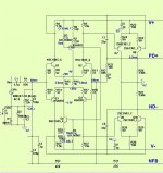
1. does kypton v2 R14 and R15 can it be increased to 6.8k for voltages as much as 100? did the sim it worked fine. I think as long as 12V is supplied to the IPS it should be fine? anything to be considered for +/-100V max supply rails?
2. which of the transistors to be thermally coupled? apart from the input stage.
3. Does the output transistors can be TO 92? as I see the heat dissipation is about 250mW is it safe if mounted on heatsink?
Im thinking to use this type of heatsink for VAS stage
http://www.angelfire.com/sd/paulkemble/gembias.gif
http://www.angelfire.com/sd/paulkemble/sound5l.html
Last edited:
what is the role of C4, C5 even if I remove it the output is same? what do they do?Both are good , I've only run BJT's on either.
Here is another that I actually have used e-waste 70's Jfets with.
A very common 70-80's Japanese Jfet input stage.
The 1'st Jfet stage run +/-12V , any FET will work.
OS
Can't you see ? They decouple the led's so current variations in the input
pair will not modulate the LED's Vf.
That Vf is very important , since it sets the VAS I.
OS
pair will not modulate the LED's Vf.
That Vf is very important , since it sets the VAS I.
OS
ok since the LEDs are clamping so using different Vf values seems ok.Can't you see ? They decouple the led's so current variations in the input
pair will not modulate the LED's Vf.
That Vf is very important , since it sets the VAS I.
OS
ok since the LEDs are clamping so using different Vf values seems ok.
No , a red- the lowest at 1.7-1.8v. In fact , don't use a high brightness red -
sometimes >2.0Vf.
If you use >1.9Vf led's , current will be two high on the last two stages.
OS
No , a red- the lowest at 1.7-1.8v. In fact , don't use a high brightness red -
sometimes >2.0Vf.
If you use >1.9Vf led's , current will be two high on the last two stages.
OS
But the one that you have mentioned is Vf 2V
HTTP 301 This page has been moved
But the one that you have mentioned is Vf 2V
http://pdf.datasheetcatalog.com/datasheet/fairchild/QTLP690C-R.pdf
probed across the leds in the sim giving about 1.7V but in datasheet its not showing.
You were told not to use a super bright.
Choose an ordinary red LED with a 1.6Vf to 1.8vf
Run it at 1 to 2mA.
Choose an ordinary red LED with a 1.6Vf to 1.8vf
Run it at 1 to 2mA.
just checked the leds i have and found that the voltage across the LED 1.7V when lit and by increasing the voltage little bit higher it was showing the same which I think is what required to make this work.You were told not to use a super bright.
Choose an ordinary red LED with a 1.6Vf to 1.8vf
Run it at 1 to 2mA.
But the one that you have mentioned is Vf 2V
HTTP 301 This page has been moved
probed across the leds in the sim giving about 1.7V but in datasheet its not showing.
That qtlp690 shows a 1.72V LT spice Vf.
Older ewaste (dim red) leds are usually GaAs (a little P).
about 1.7V.
New ALGaAs or GaP reds are much brighter with >2.0Vf.
So, old GaAs based deep dim red's are best for Vf , Tc , and will
last the longest (and not blind you).
At the 1ma K-V current , an old red would last a century.
OS
Can you make the Kypton V2 into current feedback?That qtlp690 shows a 1.72V LT spice Vf.
Older ewaste (dim red) leds are usually GaAs (a little P).
about 1.7V.
New ALGaAs or GaP reds are much brighter with >2.0Vf.
So, old GaAs based deep dim red's are best for Vf , Tc , and will
last the longest (and not blind you).
At the 1ma K-V current , an old red would last a century.
OS
do you think current feedback sounds better?
How about using the same N channel duals in symmetrical configuration like Yamaha A500?
http://elektrotanya.com/PREVIEWS/63463243/23432455/yamaha/yamaha_a-500.pdf_1.png
http://elektrotanya.com/PREVIEWS/63463243/23432455/yamaha/yamaha_a-500.pdf_1.png
What are you talking about, there's one diff pair for the left channel and one diff pair for right channel. That IS "symmetrical" but only as the channels are the same. If that's symmetrical in your book you need a different book.
Craig
Craig
How about using the same N channel duals in symmetrical configuration like Yamaha A500?
http://elektrotanya.com/PREVIEWS/63463243/23432455/yamaha/yamaha_a-500.pdf_1.png
yes , that is both channels.
For a true symmetrical , you need P/N.
An example (below) about as simple as it gets - symetri.
Just the DC blocking cap on the symetri kept the offset to <10mv
on the two builds of it. A servo would give <1mv.
No real issue with anally matching the P/N. THD might be better
with closer pairs.
OS
Attachments
ohh I thought its same channel..😱What are you talking about, there's one diff pair for the left channel and one diff pair for right channel. That IS "symmetrical" but only as the channels are the same. If that's symmetrical in your book you need a different book.
Craig
yes , that is both channels.
For a true symmetrical , you need P/N.
An example (below) about as simple as it gets - symetri.
Just the DC blocking cap on the symetri kept the offset to <10mv
on the two builds of it. A servo would give <1mv.
No real issue with anally matching the P/N. THD might be better
with closer pairs.
OS
agreed but when you see there are few things to consider that lets take 2sk170 and 2sj74 where 2sj74 is not its true compliment like a perfectly symmetric. I always thought to use two n channels and then use some flip method to make the compliment output that it was given in your sansui classic.
Infact the THD plot looks great with dual n differential input than differential compliment from the symmetri amp output as I have posted the FFT in the previous posts.
Both are good , I've only run BJT's on either.
Here is another that I actually have used e-waste 70's Jfets with.
A very common 70-80's Japanese Jfet input stage.
The 1'st Jfet stage run +/-12V , any FET will work.
OS
Is it possible to use the vas of this
http://www.diyaudio.com/forums/atta...ary-input-stage-n-channel-jfets-kypton-nd.asc
with dual n channel jfet inputs?
Is it possible to use the vas of this
http://www.diyaudio.com/forums/atta...ary-input-stage-n-channel-jfets-kypton-nd.asc
with dual n channel jfet inputs?
You should of read the timeline of the Kypton-V .I tried the super pair
"ND" VAS with it.
The V had too much gain and "excited" the pole of the super-pair.
In other-wards , the original V oscillated.
The final V used a standard VAS with clip diodes at the input pair -
Thimios (testing) was perfect.
OS
rhythmsandy,
Do you have these designs running in sim? Easier to see what works in sim first, just like OS has done.
IIRC I did capture one design a while back, the Sansui AU-X1 design. i almost have the kypton V2 final, in sim, as I did not see it posted. The original v1 sim got posted.
Who knows one day I might decide to build these models. Right now I got my LME49830 with Semelab Latfet amp going, sounds fine. How many power amps do I need?
Last edited:
So i found my sims, I have the one from Bob C's book figure 7.13 and the Sansui AU-X1 also used in BA-F1.
I see a few differences in the Sansui design and kypton-v2. One notable, is Sansui used cascodes on Q5,6,7,8 as referenced to the kypton-v2 schem.
I will post the sansui design.
I see a few differences in the Sansui design and kypton-v2. One notable, is Sansui used cascodes on Q5,6,7,8 as referenced to the kypton-v2 schem.
I will post the sansui design.
Attachments
- Status
- Not open for further replies.
- Home
- Amplifiers
- Solid State
- Bob Cordell complementary input stage with N channel Jfets