If we connect the output stage there is always some difference at the output of the VAS stage like..
for positive output it will be like 2.05V and negative at -0.80V so why is this happening Im not getting equal or atleast very close output from the vas once loaded with the output stage.
I thought some imbalance could be there and added the basic current mirror at the input stage but no use its still the same.
please find the file that Im using right now. Everything simulates well but in practice its not working as expected.
https://dl.dropboxusercontent.com/u/7421969/002_MOSFET_Kyptonasc.asc
https://dl.dropboxusercontent.com/u/7421969/002_MOSFET_Kyptonasc.asc
The role of transconductance here with the jfets and the source resistors how about reducing the source resistors if the transconductance is very low as in the order of 1.4mS than 22mS?Both are good , I've only run BJT's on either.
Here is another that I actually have used e-waste 70's Jfets with.
A very common 70-80's Japanese Jfet input stage.
The 1'st Jfet stage run +/-12V , any FET will work.
OS
There is one strange issue happening here with the lateral mosfets.
I have used a simple resistor for biasing the ALF16N20W mosfets in the output stage.
The bias actually fits properly here measured about 0.5Amps per mosfet at 25V and it works fine but there is one strange problem observed as the current increases when i increase the input signal and the current goes up and sits up higher value like 0.9Amps and that idle current will not come down even after signal is made to 0. It looks like it reduces very very slowly but not quickly what could be wrong?
Is there a cap in the circuit that gets charged up by the signal and influences the bias setting?
Schematic?
Jan
Schematic?
Jan
Is there a cap in the circuit that gets charged up by the signal and influences the bias setting?
Schematic?
Jan
no even i thought that and i havent used any cap after the PD+ and ND-
Attachments
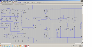
You need a path between Q11 and Q12 emitters. Install a resistance there to get some quiescent current flow in your drivers.
You need a path between Q11 and Q12 emitters. Install a resistance there to get some quiescent current flow in your drivers.
Yes installed a 150ohm resistor. Im getting only 100ma bias per fet not increasing more than that. But the same resistor is working great in class AB with transistors.
Then either increase the value of the added resistor between Q11 and Q12 emitters, or increase the value of the bias resistor. Since you use BJT drivers I'd consider a Vbe multiplier that is thermally coupled to the drivers instead of resistive bias.
yes I did the points you have mentioned aboveThen either increase the value of the added resistor between Q11 and Q12 emitters, or increase the value of the bias resistor. Since you use BJT drivers I'd consider a Vbe multiplier that is thermally coupled to the drivers instead of resistive bias.
1. changed the resistor to higher value like 820 ohms but the prob was still there
2. Added the vbe multiplier to the output stage heatsink even then it didnt work
3. Moved the vbe multiplier to the driver stage heatsink and yes now things stabilized.
One problem is observed the bias is stable anywhere upto 0.6Amp per fet at 25V but the bias increment is kinda slow like as if a BJT transistor on the output.
But the bias current is not going beyond 0.6amp per fet. what if I want more bias at this voltage like 1Amp.
the measured current through PD+ and PD- is 2.5ma so is this the limiting factor
the beta of the drivers being 210 so even if we take best match we get 0.525Amp of output current from the drivers.
one more thing observed is that when the bias resistor value is at 110 ohms the idle current in output fet is .6Amp and not beyond that and the strange part is if i reduce this resistor further then the bias current in the output mosfet is going down what might have went wrong here?
yes I did the points you have mentioned above
1. changed the resistor to higher value like 820 ohms but the prob was still there
2. Added the vbe multiplier to the output stage heatsink even then it didnt work
3. Moved the vbe multiplier to the driver stage heatsink and yes now things stabilized.
One problem is observed the bias is stable anywhere upto 0.6Amp per fet at 25V but the bias increment is kinda slow like as if a BJT transistor on the output.
But the bias current is not going beyond 0.6amp per fet. what if I want more bias at this voltage like 1Amp.
the measured current through PD+ and PD- is 2.5ma so is this the limiting factor
the beta of the drivers being 210 so even if we take best match we get 0.525Amp of output current from the drivers.
one more thing observed is that when the bias resistor value is at 110 ohms the idle current in output fet is .6Amp and not beyond that and the strange part is if i reduce this resistor further then the bias current in the output mosfet is going down what might have went wrong here?
Jason can you provide me some inputs..
I find it little strange that when the drivers are not mounted the bias current on the output stage per fet was easily getting to more than 1Amp but when the drivers are added its just cant cross 0.6Amp per fet why is this happening?
my oscilloscope went for service any other way to check it? Sound wise its good somehow not so natural as BJT input.Oscillation? You might want to probe around with a wideband scope when the current is high.
Last edited:
There is one more thing observed that by increasing the voltage in dimmer stat i can see this bias getting increased accordingly but the limit is going up like 0.7AmpsOscillation? You might want to probe around with a wideband scope when the current is high.
It isn't as reliable a test as using a scope, but if it's oscillation and the oscillation is high enough in frequency, you might see the current level change when you touch some circuit nodes with a finger (with the rest of your body not touching anything related to the circuit of course!). You also might be injecting hum, so that may still not tell you anything. If the current changes when your finger only gets near something, then that would be it but that would have to be way higher frequency than these audio parts are likely to sing at!
Hmmm...
You might try making a basic RF probe for your DVM. (look it up, simple, few parts) Then you should be able to find an RF oscillation pretty easily, if it's there. At least it should give you a way to track it, till your scope comes home.
You might try making a basic RF probe for your DVM. (look it up, simple, few parts) Then you should be able to find an RF oscillation pretty easily, if it's there. At least it should give you a way to track it, till your scope comes home.
sorry guys my oscillator died as it was too old and about to order one.
I still have the problem with the oscillation. Its happening only when the bias is high as much as 400ma per mosfet. How to make the amp stable here.
1. Changed the source resistors from 22 ohm to 63ohm but no use
2. changed the 6.8pf to 33pf trans miller comp but no use
3. reduced the bias to almost 0 very little oscillating noise from the speakers
4. This is happening only with the Alfets at the output but not with the toshiba BJT at the outputs.
5. When the bias is increased wherever i touch like the driver mounted heatsink i get hum from the speaker.
sorry guys my oscillator died as it was too old and about to order one.
I still have the problem with the oscillation. Its happening only when the bias is high as much as 400ma per mosfet. How to make the amp stable here.
1. Changed the source resistors from 22 ohm to 63ohm but no use
2. changed the 6.8pf to 33pf trans miller comp but no use
3. reduced the bias to almost 0 very little oscillating noise from the speakers
4. This is happening only with the Alfets at the output but not with the toshiba BJT at the outputs.
5. When the bias is increased wherever i touch like the driver mounted heatsink i get hum from the speaker.
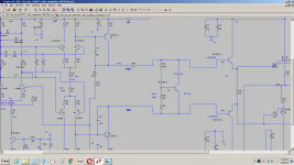
well finally figured out what has to be done that increased the R21 > 63ohm resistor to higher value as 180ohm and the result is the bias got stabilized.
Added the 33pf cap between the Drain and the Gate for the output stage for the N channel and the oscillation stopped.
But there is some sound quality difference and I think its happening main because of the increase in the 63ohm resistor to 180ohm. The bias got stabilized but the quality seems slight hit.
I have a question that even when I got 5ma at the VAS output but why is the bias going out of control ?are the Vbe multiplier values are wrong?
Attachments
- Status
- Not open for further replies.
- Home
- Amplifiers
- Solid State
- Bob Cordell complementary input stage with N channel Jfets