Hello,
Since few days I have a nice little amp (Raphaelite DP84).
Having some 5Y3GT, I tried an RCA instead of Chinese 5Z2P.
At startup there was a blue flash in the tube and noise in the speakers, then OK.
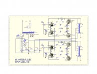
Looking at the schematic, is it not too hard for the 5Y3 to "load" capacitor 270uF (C9)?
Should I put a 100 ohm resistor between the rectifier bridge and the plates of the 5Y3? something else?
Since few days I have a nice little amp (Raphaelite DP84).
Having some 5Y3GT, I tried an RCA instead of Chinese 5Z2P.
At startup there was a blue flash in the tube and noise in the speakers, then OK.
Looking at the schematic, is it not too hard for the 5Y3 to "load" capacitor 270uF (C9)?
Should I put a 100 ohm resistor between the rectifier bridge and the plates of the 5Y3? something else?
Attachments
"At startup there was a blue flash in the tube and noise in the speakers, then OK".
Not for long. 270uF as a reservoir capacitor with hollow state diodes is way, way, way too much. Look at the spec for the 5Y3: Isurge= 2.5A/plate. Even though that looks like a lot, it's really nothing as compared to the Isurge of even small Si diodes.
You can use these enormous reservoir capacitors with solid state diodes, but not for hollow state. Hollow state remains high voltage, low current, and whoever designed that forgot that basic difference. Even back in "the day", it was sometimes done, but was always a compromise between cost and reliability. Then, it didn't matter because the largely atechnologically illiterate PaL didn't realize that having to replace the 5Y3s every six months was abnormal. Nor did it matter so much when you could get new ones at nearly every pharmacy, 7-11, grocery store, etc -- where ever you found those "You Test 'Em" kiosks. Even then, the biggest reservoir capacitors hung off the cathodes of a 5Y3 were 100uF -- less than half the 270uF that schemo calls for.
It's a fundamentally bad design. Either replace the hollow state diodes with Si units that can stand up to the excessive Isurge those 270uF capacitors produce, or redesign the PS reservoir capacitors sized to keep Isurge in spec, and lose the AC ripple with the appropriately designed LPF.
Otherwise, expect to be replacing 5Y3s frequently.
Thank you for your reply.
So the first cap - C8 on schematic - already charged by the rectifier bridge before the 5Y3 conducts does not help the 5Y3 ?
So the first cap - C8 on schematic - already charged by the rectifier bridge before the 5Y3 conducts does not help the 5Y3 ?
The Chinese are not the only folks who ignore cap. size limits, when working with vacuum rectifiers. Cary is another example. Grrr!!!
Look at the 5Y3 data sheet. 20 μF. is given as typical in a cap. I/P filter. Miles is quite correct in stating that unless the amp is modified, it will "eat" 5Y3s. 🙁
Eko2, please post a scan of the amp's schematic and top and bottom photos. One solution to the problem is installing a small cap. and a choke between the rectifier and that 270 μF. monstrosity. We need to see how much room is available.
A possible quick fix is the installation of a CL-90 inrush current limiting thermistor in the line between the rectifier and the big cap., but I don't know if the CL-90's cold resistance of 120 Ω is sufficient to tame the turn on surge and stop the destructive arcing.
what some do is take a big resistor say 5 k and then after some time say 20-30 secs bridge that / with a relais that picks up. It will give s slow start.
But it might still give a spark, depending on the total resistance (trannie+limiting resistor).
But it might still give a spark, depending on the total resistance (trannie+limiting resistor).
It will give s slow start.
The irony is that the tube rectifier is there for no other reason than slow start / voltage sag. A solid state bridge rectifier does the rectification (see schematic)...
Rundmaus
I missed the schematic. It seems the "designer" is using the vacuum rectifier to delay B+ rise. The Chinese 5Z2P appears to have a cathode sleeve, making it a 6087/5Y3WGTB "equivalent". However U.S. made 5Y3s are filamentary and turn on almost as fast as the "sand" diodes.
The low competence level of the designing person(s) is illustrated by the fact that 2 of the SS diodes in the rectifier bridge are unnecessary. The vacuum rectifier can serve as the bridge's "hot" side.
Cheap Chinese amp's are usually built on PCBs. Maneuvering room for design defect correction may be badly limited.
Last edited:
I think the main problem here is C8. This will be fully charged before the 5Y3 has chance to warm up and conduct. C8 will hold an enormous charge and if the anode/cathode voltage breaks down then one hell of a current will flow. I suggest putting a 1k resistor across the anode / cathode of the 5Y3 or remove C8.
Last edited:
eddie,
that could be the crucial point. The large C afterwards might be safe due to the 100R series resistor limiting the current.
Most vacuum rectifier manufacturers state a minimum resistance in the anode circuits, usually created by the power transformer impedance and additional series resistors, if necessary. In the schematic above, the anode circuit resistance is close to zero due to the charged C8.
Remove C8 and see what happens.
Rundmaus
The big 270µ is not charged by the valve,it's in front of it.So nothing wrong here,schematic ok.For a decent delay of the powervoltage the valve has to be indirectly heated.
Mona
Mona
The more I look, the LESS I like! 🙁 🙁
That's a PP 7189 setup. The "idle" current of 4X 7189s is greater than the 125 mA. capability of a 5Y3. Even without arcing, the vacuum rectifier is destined to expire quickly. Put a Sovtek 5AR4 in the rectifier socket and install a CL-90, as previously mentioned. Then, cross your fingers.
The O/P "iron" has UL taps, but the topology is full pentode. They went for power, instead of sound. Sorry, everything I see, like a paraphase splitter, screams POS.
The big 270µ is not charged by the valve,it's in front of it.
This is exactly where valve rectifiers often need current limitation, according to manufacturer datasheets. Too much capacitance afterwards is bad, to low anode circuit resistance is bad as well.
Rundmaus
Your RCA 5Y3 could be gassy - especially if it has not been used in quite some time. I'm assuming it's an old tube, RCA has been out of the business for a long time.
It's possible that when you first turned the amp on, the 5Y3 flashed-over. The diode bridge/270uF cap on the plate will bring the plate up almost instantly, meanwhile the 5Y3 is warming up and beginning to conduct.
The 100 ohm current limiting resistor in the cathode (filament of the 5Y3 - Eli is right, the US made 5Y3 from RCA is directly heated) will isolate the 5Y3 from the second 270uF cap (C9). Depending on how fast the 5Y3 turns on (it should be a high-resistance when off, with current flow ramping up as the 5Y3 warms up), the current surge should be <1A.
Possibly if you turn the amp on and let the 5Y3 run for several hours to try to bake it out you will not see this problem in the future.
Best luck! 😎
~ Sam
Let's wait for the OP to upload some photos. Maneuvering room is needed to straighten the B+ PSU out. I have some ideas, starting with a true hybrid bridge employing a 5AR4, but until the available space is known, everything is speculation.
Let's wait for the OP to upload some photos. Maneuvering room is needed to straighten the B+ PSU out. I have some ideas, starting with a true hybrid bridge employing a 5AR4, but until the available space is known, everything is speculation.
Why, of course oh Honorable Master Of This Thread!
If it doesn't work - well, blue flashes sound quite stylish to me! Maybe it's worth the expense of frequently changing rectifier tubes. As the tube does no real rectifier service, no bad things like reverse breakdown can happen...
Rundmaus 😉
Rundmaus 😉
Why, of course oh Honorable Master Of This Thread!
Me, master? Hardly! I have some knowledge and a loud mouth. We pool ideas to get a highly questionable design into reasonable shape. I've seen more than enough to know your head contains good stuff.
Now I'm scared to turn on my little amp 😀
By the way I have some Philips GZ34 and little open frame chokes (Hammond 156R 1.5H 200mA 56 DCR).
I'll post photos asap.
By the way I have some Philips GZ34 and little open frame chokes (Hammond 156R 1.5H 200mA 56 DCR).
I'll post photos asap.
Now I'm scared to turn on my little amp 😀
By the way I have some Philips GZ34 and little open frame chokes (Hammond 156R 1.5H 200mA 56 DCR).
I'll post photos asap.
Put the Chinese rectifier back in and use the amp, as is, until a consensus forms about the changes needed.
The Philips GZ34/5AR4 is FINE and may be better than the amp deserves. A Hammond 156R dovetails nicely with my cogitations.
- Status
- Not open for further replies.
- Home
- Amplifiers
- Tubes / Valves
- blue flash inside 5Y3GT