How did you listen to the clips?
With headphones only. My headamp has no feedback: it's a MOSFET source follower, bipolar supply, chassis mount source resistor, lots of current and heat. Only one active device in the signal chain, not even a CCS (although I am considering that). A very spartan design, the pure sound of one transistor clapping.
With headphones only. My headamp has no feedback: it's a MOSFET source follower, bipolar supply, chassis mount source resistor, lots of current and heat. Only one active device in the signal chain, not even a CCS (although I am considering that). A very spartan design, the pure sound of one transistor clapping.
Oh, I thought you could hear the bass sound of amplifier G (recorded in the clip) using wide range speaker.
One mosfet source follower? Such has low damping (high output impedance) and is not easy to drive. Coz output impedance is an inverse function of transconductance, you want a mosfet with high trans-conductance and if the capacitance is high, you want to run it with high bias current. I think suitable mosfets are IRF530, IRF510, IRF610. I believe you use one of those?
Yes, the sound is the most "pure" at midrange frequency but overall (e.g. bass) I found it unusable (unless you have a secret mosfet or power JFET 🙂)
DD,
Why is an issue with a single source follower?
If the gm is say 0.2S, the Zout based on the recip gm is around 5.
Yet the target impedance, the cans, might be 60R, DF is 12, and if it's a 280R, a DT880 Beyerdynamic, it's up around 270R, DF 54.
These figures are high by speaker standards, and more than enough for more forgiving headphones.
HD
DD,
Why is an issue with a single source follower?
If the gm is say 0.2S, the Zout based on the recip gm is around 5.
Yet the target impedance, the cans, might be 60R, DF is 12, and if it's a 280R, a DT880 Beyerdynamic, it's up around 270R, DF 54.
These figures are high by speaker standards, and more than enough for more forgiving headphones.
HD
Hi HD, I have never built or listened to a headamp. I just deduced from typical headphone impedanceand my experience with said IRFs.
I dont think DF is a reliable measure. Zout=5 seems to be high for me. If DF=12-54 is high by speaker standard, then you may be right, and I realized my mistake of having too high standard 🙂 Seriously, the biggest vomponents of amp cost are the power supply and enclosure, so logically, why waste those expensive components to support low standard cct if we know that we can have higher one for free???
People build inferior amps because they dont know about quality difference. They could ask. People build inferior amps because they are proud of their own design. Im not blaming people, but myself. I wish im part of the younger generations who build great amps as their first builds. I need to build hundreds of amps until I know what I know now. People shouldnt follow that path 😀
The Pocket Class A amp has output impedance (from LTspice) of 2.9 ohms. I think the amp with 2SA1837 is similar.
If you want to hear what a user's impressions are of the Pocket Class A amp, there is no lack of bass authority or sound quality:
http://www.head-fi.org/t/837656/new...1-now-available-as-complete-pcb#post_13310030
Other users have reported similar experiences.
One of the amps uses a power JFET lu1014d - output impedance is much lower and that amp DC coupled. But sound quality was not preferred.
Last edited:
The Pocket Class A amp has output impedance (from LTspice) of 2.9 ohms. I think the amp with 2SA1837 is similar.
This might tell that 2.9 is ok and 5 might not be sufficient.
One of the amps uses a power JFET lu1014d - output impedance is much lower and that amp DC coupled. But sound quality was not preferred.
Low zout is not the reason for it being not preferred. Is it amp A? There is something wrong with the sound. I suspected that the problem was with the preceeding circuit. Is it a DAO? What is the reason to add extra circuitry? I have no experience with power jfet
One of the amps uses a power JFET lu1014d - output impedance is much lower and that amp DC coupled. But sound quality was not preferred.
But, you didn't have a clip of just the JFET follower since it had a driver stage (the BF862 pre?). Perhaps with a different preamp stage, it would have won. So many variables in these tests...
I meant to post the impressions that I wrote down of each amp in this audition, but I accidentally deleted the text file. Anyway, the standout to me was Amp C. The vocal had much more transparency to me on that amp. Before X posted the identities of the amps, I figured that Amp C had to be either the Super CMOY or the FiiO A5. I was wrong! I thought that the difference in clarity I was hearing must be resulting from ultra-low distortion, and I figured that those Class D amps would have the least THD. Oh well...yet another sonic victory for Class A in my book. Now I just need to learn more about this mysterious CFB amp by Aska...
There are no class D amps here. Only opamp/chipamp Class AB based (A5 & Agdr Super CMOY) and Class A.
C is actually very good. It is similar to B in topology but uses BD140 BJT vs Toshiba 2SA1837. The Toshiba transistor here has sort of a legendary cult status though.
Aksa's CFP or complementary feedback pair, also known as Sziklai pair (modified with JFET in master vs a NPN BJT).
C is actually very good. It is similar to B in topology but uses BD140 BJT vs Toshiba 2SA1837. The Toshiba transistor here has sort of a legendary cult status though.
Aksa's CFP or complementary feedback pair, also known as Sziklai pair (modified with JFET in master vs a NPN BJT).
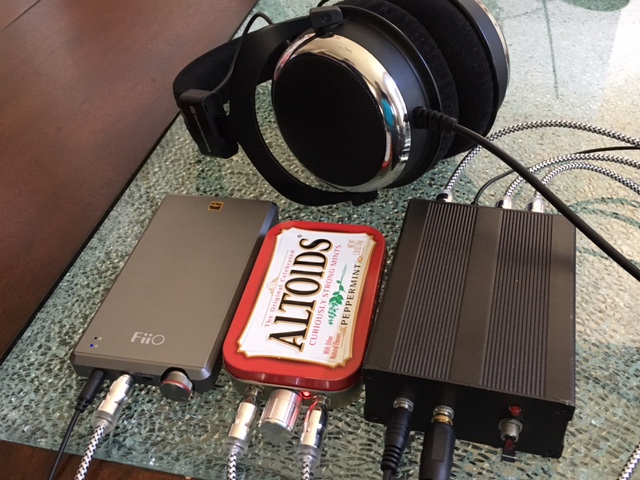
AB Test Box
I just whipped up this AB tester box. Using two DPDT 12v relays. N/C is connected to amp A from input. The second relay switches the outputs coming back from the amps to the headphone. Both relays operate instantly and simultaneously. Pushing a momentary on switch (lights LED for "B") and flips relays to N/O for amp B. I am using a 9v battery with a small DC to DC step up booster to get 12v. 6 x 3.5mm jacks and a small box and some soldering later it's done.
Sounds completely transparent of course as it is a wire. When volume matched the switching is almost seamless and imperceptible. Great tool to have.
Attachments

Last edited:
People build inferior amps because they dont know about quality difference. They could ask. People build inferior amps because they are proud of their own design. Im not blaming people, but myself. I wish im part of the younger generations who build great amps as their first builds. I need to build hundreds of amps until I know what I know now. People shouldnt follow that path 😀
I am always looking for a new architecture to try. Can you recommend something specific?
I am always looking for a new architecture to try.
Me too (but not any new architecture). Bur for each (topology, output type, etc.) I search for the best. For example, it is common to have NPN leftovers. So for high speed NPN output device (and low power amplification), my chosen circuit topology is the JLH. If there is other quasi design that seems to be comparable in quality, I build and compare, and so I'm only left with the best.
Can you recommend something specific?
I don't build headamp. So I don't have the best headamp with me. But direct comparison is very critical if we want to choose the best circuit. For speakers this is very expensive, for amps still doable but only a few people like X who has the chance to directly build and compare.
But we can use X's efforts for our advantage. Listening for the 8 headamps and compared them with the original sound clip, I knew that these amps are far from perfect. When I heard amp F, I thought, "This one can be easily the best headamp if it's weakness is improved, at least better than the other 7."
And I have suggested how to improve it in previous post. I will definitely do it if I have the parts and looking for a headamp (Then I will use that for comparisons to find better ones). Increasing voltage may ruin what is already good with F, but increasing current, I can't think of any possible drawback.
When searching for the best sound, parts are the key. Then we just need to put that part in its optimum operating condition. In X's circuit (amp F), we might be able to find better JFET than BF862, but the chance is very very small (coz I don't have BF862 so I cannot compare it with my JFETs). JFETs are rather hard to find. There is much higher possibility to find better part for the output mosfet (ZVN), especially because the ZVN weakness is the highish input capacitance (more than twice that of IRF610). It is just that there are things that determine the final sound quality that you cannot see from properties like Yfs, Ciss, Rds, individually. I can predict from datasheet, but direct listening is necessary to be sure.
One of the main goals of F was a very compact circuit, for obvious reasons. SMT parts were used extensively on the main class A poweramp side. You could use 2SK170BL and IRF610 and run the bias higher, but it wouldn't be pocket sized or battery powered. The circuit from amp B could also be made with 2SK170BL, and in fact I made the prototype with the 2SK170. I don't feel that the BF862 is worse off sonically. It certainly is more accessible and less expensive.
I have irf 610 and 2sk 170 BL.
I would like to build this if someone can post the schematic. Thanks
I would like to build this if someone can post the schematic. Thanks
I have irf 610 and 2sk 170 BL.
I would like to build this if someone can post the schematic. Thanks
I couldn't find a model for IRF610 but IRF640 might be close enough. You could just take the same circuit for BF862 and ZVN4306 and drop in 2SK170 and IRF610 and it will work pretty well. It will run a little hotter.
Here is a circuit reoptimized for the 2SK170 and IRF640. It's running about 55mA bias in IRF640:
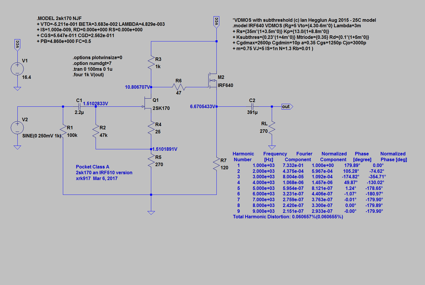
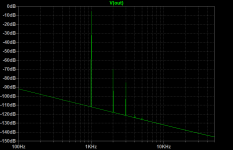
FFT is pretty good and should get about 0.06% THD at 700mV drive into 270R load:

Attachments

I couldn't find a model for IRF610
.model IRF610 NMOS(Level=3 Gamma=0 Delta=0 Eta=0 Theta=0 Kappa=0.2 Vmax=0 Xj=0
+ Tox=100n Uo=600 Phi=.6 Rs=.5804 Kp=20.77u W=.45 L=2u Vto=3.886
+ Rd=.5781 Rds=888.9K Cbd=220.5p Pb=.8 Mj=.5 Fc=.5 Cgso=517.7p
+ Cgdo=61.68p Rg=.2597 Is=1.647p N=1 Tt=295n)
It's good to share.
Thanks for that Mlackey. I searched around diya for at least 15min and could not find a readily usable model.
You could use 2SK170BL and IRF610 and run the bias higher, but it wouldn't be pocket sized or battery powered. The circuit from amp B could also be made with 2SK170BL, and in fact I made the prototype with the 2SK170.
When the ZVN is replaced with IRF610, the sound will change. It might not an improvement to the amp F.
For best amp, neutral in timbre etc, the transistor must operate in its linear region. May be there is not many people who can hear this, and that's why its importance is ignored.
Verticals are far from a linear device. It has to be biased impractically very high to be a bit linear. I'm sure IRF610 will not make the best headamp.
2SK170 may be more expensive, but I doubt it can be as good as BF862. If the JFET has to be purchased, better try the 2N6xxx as used in the Goldmund amplifiers.
Weren't you just saying IRF610 is better because of lower capacitance? I agree that the 2Sk170 may not be any better then BF862. Although the combo of SK170 and IRF610 sounds very nice in F5 HA.
Weren't you just saying IRF610 is better because of lower capacitance? I agree that the 2Sk170 may not be any better then BF862.
I said the ZVN has more than twice the capacitance of IRF610.
Yes, IRF610 is good for having the right combination of low Ciss and high Yfs. But there are other parameters, then these parameters should work together with other parts and in a given topology.
This is a very simple circuit, so not much can be done. It is LUCK if we can find a JFET-MOS combo that will fit in this simple circuit with acceptable performance, especially by my standard. If damping is improved, THD will suffer.
That's why I think you should keep the BF862-ZVN combo and improve on that. I know that not much current is possible with ZVN. But if amp F is already good, then even slight improvement is super.
Although the combo of SK170 and IRF610 sounds very nice in F5 HA.
Source follower? I don't think so.
BTW, can you post the model for the ZVN and the BF862? Who knows I will have time to play around with it.
Last edited:
- Status
- Not open for further replies.
- Home
- Amplifiers
- Headphone Systems
- Blind Virtual Audition of Several Headamps