I measured the transformer and the output is about 7.5VAC unloaded. That is 10.61Vp, which would give me a bit of head room for the regulator. I have not considered the heat of the BR though. Would this really be an issue? The BR does not have a hole for mounting, but it's specs say it can handle quite a bit and never mentioned heat in the data sheet. Rev. Voltage 50 to 1000V Forward Current 1.5A. I used calipers for all of my parts, so they are pretty accurate footprints. It still seems like a good idea to move them a bit especially since I have a lot of space. I will investigate the trim pot problem. Thanks for your help Tom.
I measured the transformer and the output is about 7.5VAC unloaded. That is 10.61Vp, which would give me a bit of head room for the regulator.
What's the DCR of the winding? That along with the DCR of the primary and the expected primary current draw will give you an estimate of the secondary voltage under load. Or... You could just load the secondary appropriately and measure the voltage. You'll find that it's lower than 7.5 V.
It's true that the peak value of a 7.5 V RMS sine wave is sqrt(2)*Vrms or 10.6 V in your case. However, to achieve that voltage across the reservoir cap, the conduction angle would have to be zero and, thus, the ripple current would be infinite. Ain't happenin'! In real life, under load, with finite conduction angle, you can expect 1.2x~1.3x Vrms.
I have not considered the heat of the BR though. Would this really be an issue?
I dunno. You tell me. What's the max junction temp the bridge can handle? What's the thermal resistance from junction to ambient? How much power are you dissipating in it? What's the expected ambient temperature inside the chassis where the supply will be mounted. If the rectifier doesn't have provisions for heat sinking, it's probably not an issue. It's just something I'd check to make sure.
~Tom
Tom, it's the 3n249. @25°C ambient temperature Operating junction and storage temperature range: -55 to +150°C High temperature soldering guaranteed: 260°C/10 seconds at 5 lbs. (2.3kg) tension Would I not be able to use the circuit with the filament transformer tap?
Tom, it's the 3n249. @25°C ambient temperature Operating junction and storage temperature range: -55 to +150°C
Great. Now you just need to calculate the dissipated power and the temperature rise. What's the voltage drop across the bridge? What's the current through it?
Would I not be able to use the circuit with the filament transformer tap?
That all depends on the max dropout of the voltage regulator you're using.
I'm an engineer. I design for operation under worst case conditions. I.e. I would guarantee that the circuit will perform as designed when the AC input voltage is 5 % low, the diode drop in the rectifier is the highest, the capacitance of the reservoir cap is the lowest (affects ripple voltage), and worst case LDO drop-out voltage.
The diode drop you can find in the data sheet for the diode bridge. The ripple voltage can be approximated from C = Q/V, Q = i*t, where i is the DC current drawn from the cap, t is time (the cap is charged twice every mains cycle, hence t = 10 ms on 50 Hz systems, 8.3 ms in 60 Hz systems). So when you know C in Farad you can calculate the ripple voltage V from above equation. The max drop-out for your regulator can be found in the data sheet.
Vtrafo > (Vout + Vdropout_max + Vripple + Vdiode-drop)/(1.2*0.95)
So you tell me (it's your homework project after all)... Can you meet above with the 6.3 V winding? If yes --> no problem then. If no --> what voltage do you need and how do you get there? Can you add a couple of turns on the 6.3 V winding?
~Tom
I am just an engineering student, so I have a lot to learn! The transformer is enclosed and has bolts to seal it. I may be able to open it, but I think the chances of stripping the flat-head bolt is pretty high. I do have a separate tap on my 12V-0-12V transformer, but there would be a tremendous amount of heat generated by the LM317 regulator for 6.3VDC and it can only supply 250mA; not enough current.. The voltage difference needs to be 1.5V minimum at 100°C and 1.75V at 25°C. If the transformer outputs 6.3VAC, then it would still meet this condition? If I am right, that would be 2.611V difference. Although, I don't know about the thermal relation. Also, I was wondering the proposed values for the resistor for the trimpot? I looked at your schematic for your PSU but couldn't figure out how I could implement it.
Last edited:
I am just an engineering student, so I have a lot to learn!
That's why I ask you questions rather than provide answers for you. You won't learn anything if I answer your questions for you.
The transformer is enclosed and has bolts to seal it. I may be able to open it, but I think the chances of stripping the flat-head bolt is pretty high.
Yeah... I wouldn't mess with that either. I've added windings to toroids before. Works great. But E-I... Forget it. Unless you truly enjoy rebuilding transformers, that is...
The voltage difference needs to be 1.5V minimum at 100°C and 1.75V at 25°C.
And I believe about 2.5 V at -40 C. I tend to use 2.5 V, but I also tend to be conservative in power supply design.
If we go with your numbers, you now have one piece of the puzzle.
Vdropout_max = 1.75 V.
You also have: Vout = 6.3 V.
You can find Vripple from C = Q/V, Q = i*t --> Vripple = (i*t)/C. I gave you t (seconds) in my previous post. You should know i (in Ampere) and C (in Farad) already as you know which kinds of tubes you're feeding and you've already placed the cap on the board... So calculate Vripple.
Vdiode-drop is the drop across the diode bridge (the total drop, not just one diode drop). You should be able to find the drop for one diode within the bridge from the datasheet for the bridge. If it isn't specified, I'd use the drop for something like an 1N540x diode as a reasonable approximation. Remember that for a full wave rectifier, the total drop, Vdiode-drop, is 2*Vf, where Vf is the forward voltage drop of just one diode.
If the transformer outputs 6.3VAC, then it would still meet this condition?
I've given you all the pieces. You just have to do the math.
Also, I was wondering the proposed values for the resistor for the trimpot?
The general recommendation for LM317's is to set up a 5~10 mA current in the resistive divider for the feedback. That's why you typically see 120 ohm from Vout to ADJ. Adding a pot in parallel with the 120 ohm resistor will cause a higher current to flow in the feedback network, hence a higher output voltage. Recall, the LM317 will maintain 1.25 V across the resistor from Vout to ADJ. If you increase the resistance of the pot, the total R will increase. Decrease the pot and R will drop. That gives you voltage adjust. I strongly suggest that you add a series R with the pot to limit the range of adjustment.
But, honestly.... You don't really need adjustability. 1 % resistors are cheap and you can find a pair of values that will give you 6.3 V out -- or at least within a percent of 6.3 V. Close enough...
~Tom
The BR has 1.0-1.3Vdrop MAX Vripple @300mA = (300x10^-3*8.3x10^-3)/(1000x10^-6) = 2.49V Vripple @150mA = 1.245V That seems extremely high!
The BR has 1.0-1.3Vdrop MAX
Yeah, that's what it says on page 1. Have a look at page 2 (specifically, the Typ. Forward Characteristics figure). Note that this is PER LEG. In a FW rectifier, you conduct through two legs at the same time. Hence Vdiode-drop is 2x the figure you read in the datasheet.
Vripple @300mA = (300x10^-3*8.3x10^-3)/(1000x10^-6) = 2.49V Vripple @150mA = 1.245V That seems extremely high!
It's a worst case calculation. It assumes that the cap is charged instantaneously once per t seconds and discharges linearly between these charge packets. In reality, because of the non-zero conduction angle I harped about a few posts back, the cap will charge over a longer fraction of the period so in reality, the discharge time, t, will be shorter.
You can probably find a better estimate of the ripple voltage by calculating the conduction angle, and get a better estimate for the discharge time. But if you want to be more accurate about it than the quick, back-of-envelope calculation I'd turn to Spice. A quick simulation in LTSpice (free download from Linear Tech) shows 1.71 V ripple (1000 uF cap, 300 mA load, 60 Hz mains). So 2.5 V is not way off by any stretch of imagination. 300 mA is a sizable current and 1000 uF is a fairly small cap... Also note that most newer electrolytic caps have tolerances on the order of +/-20 %, so that 1000 uF cap might be 800 uF (--> 2.1 V ripple). Older ones are typically +100%/-50%. Yep. -50 %!!
So... We have:
Vout = 6.3 V
Vdropout_max = 1.75 V (using your number)
Vripple = 1.7 V (using the figure from the Spice sim)
Vdiode-drop = 2*Vf = ??
You find Vf, hence, Vdiode-drop from the graph in the data sheet (it depends on current). Then run through
Vtrafo > (Vout + Vdropout_max + Vripple + Vdiode-drop)/(1.2*0.95)
again.
As I think you've started to figure out, 6.3 V AC is not enough to produce 6.3 V regulated DC @ 300 mA with an LM317 and a 1000 uF cap. So what are your options:
- Use a different regulator with lower drop-out (see the LDO (Low Drop-Out) section of major chip manufacturers' websites)
- Increase the cap to lower the ripple voltage
- Pick a diode bridge with lower drop-out. Shottky diodes have lower drop... Not much lower, though.
- Increase Vtrafo by selecting a different trafo or adding windings.
Now you know how to design a linear power supply. You should be able to run through the math and see what an infinite capacitor would do (Vripple = 0). Or an ideal regulator (Vdropout_max = 0). Or an ideal diode bridge (Vdiode-drop = 0). That would help you narrow down your options from the list above.
~Tom
Last edited:
I calculated that I would need 4980uF for .5V of ripple or 12450uF for .2V. I just need to figure out what maximum ripple I really need. I found some 15000uF 16V caps, which would yield better than .2V ripple.
I calculated that I would need 4980uF for .5V of ripple or 12450uF for .2V. I just need to figure out what maximum ripple I really need. I found some 15000uF 16V caps, which would yield better than .2V ripple.
Isn't the cart before the horse here? What is your objective? Based on that, what are your specifications? When you can answer that, you can answer the next question. Do you need a DC filament supply?
Sheldon
Isn't the cart before the horse here? What is your objective? Based on that, what are your specifications? When you can answer that, you can answer the next question. Do you need a DC filament supply?
Sheldon
Yes, I would like a regulated filament supply. I already have the components at my disposal, but this is my first design so there are a few bumps in the road. This is "supposed" to be a Hi-Fi bass guitar preamplifier.
I calculated that I would need 4980uF for .5V of ripple or 12450uF for .2V. I just need to figure out what maximum ripple I really need. I found some 15000uF 16V caps, which would yield better than .2V ripple.
That's great. Can you satisfy Vtrafo > (Vout + Vdropout_max + Vripple + Vdiode-drop)/(1.2*0.95) with that?
Recall that Vtrafo should be the voltage of the secondary with all loads connected to the transformer.
I read the forward drop of the rectifier to be Vf = 0.85 V @ 300 mA. So:
Vout = 6.3 V
Vdropout_max = 1.75 V (your number)
Vdiode-drop = 2*Vf = 1.7 V
So with an infinite cap, you'd need:
Vtrafo = (6.3+1.75+0+1.7)/(1.2*0.95) = 8.55 V. Your trafo delivers 7.5 V unloaded as I recall.
So your trafo's no good... Which begs the question (as others have asked): Are DC heaters needed? I understand that it's nice to have, but is it needed? With indirectly heated tubes there's not that much coupling between the heater and the cathode. I run AC heaters in my 6LU8 Spud without issues.
If you really want DC heaters, I suggest getting a 10 V trafo. That gives you a little margin as well. Then, of course, you'll do the thermal calculations and figure out that the LM317 will dissipate a fair amount of power under worst case conditions (high AC mains) that you'll need to get rid of. This is exactly why I ended up with a switchmode supply for my heaters in my 300B amp. I just could not justify burning 20 W of heat in the filament supply.
~Tom
The power supply I saw on the fist page was more than enough (maybe not voltage but certainly choked and capped ) for a PP 6550, or if you want to read by it too, some 845s. Too much uFs is as bad or worse than not enough.
I am building a PS for a Se amp and the filter caps I am going to use are 6 and 4 uF micamold Paper in Oil 600V (so they are really big) and a couple of chokes you can hurt people with by dropping it on them. Using hald a Farad to get the ripple out of .2 volts when you are using chokes too is just overkill and will probably sound bad.
That is the kind of cappage used in FART cars that rattle the body parts off because of trying to put 30 meter waves into a car with a cabin 6' long. That doesn't sound good either.
Thatch
What have guitars and hi-fi got to do with one another? I thought a bit of hum (whch may be inaudible anyway) was part of the 'sound'? Unless you get your grounds and circuit loops right a DC heater supply can make things worse: you get buzz instead of hum.fingerboy21 said:This is "supposed" to be a Hi-Fi bass guitar preamplifier.
DC heaters are rarely needed in hi-fi, unless dodgy valves are used. Guitar amps even less so.
I'm just trying to get the cleanest sound I can out of this project. It is my first, so I thought that regulated DC filaments were the way to go. Since I already have all the parts, I don't know why I wouldn't just try to work it out? By Hi-Fi, I mean high BW, low noise/hum, and a psuedo-linear response.
I realize I may be a little eccentric, but that's just the way I am. I see it as; "why not make it the best I can, if I have my lab's resources right now before I graduate?"
Also you said "The general recommendation for LM317's is to set up a 5~10 mA current in the resistive divider for the feedback. That's why you typically see 120 ohm from Vout to ADJ. Adding a pot in parallel with the 120 ohm resistor will cause a higher current to flow in the feedback network, hence a higher output voltage. Recall, the LM317 will maintain 1.25 V across the resistor from Vout to ADJ. If you increase the resistance of the pot, the total R will increase. Decrease the pot and R will drop. That gives you voltage adjust. I strongly suggest that you add a series R with the pot to limit the range of adjustment.
But, honestly.... You don't really need adjustability. 1 % resistors are cheap and you can find a pair of values that will give you 6.3 V out -- or at least within a percent of 6.3 V. Close enough..."
I thought that my circuit had met the suggestions that you made.
But, honestly.... You don't really need adjustability. 1 % resistors are cheap and you can find a pair of values that will give you 6.3 V out -- or at least within a percent of 6.3 V. Close enough..."
I thought that my circuit had met the suggestions that you made.
An externally hosted image should be here but it was not working when we last tested it.
I have expressed two points about the feedback network on the LM317:
1) Run 5~10 mA in the resistive divider (as you are doing)
2) The trimpot should be set up such that when it fails, the output voltage will drop rather than increase.
Potentiometers tend to fail with the wiper open (i.e. wiper is disconnected from the resistive element in the pot when they fail). What happens to the output voltage in your circuit in that case?
~Tom
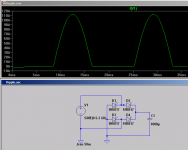
The trafo should connect from pin 2 to pin 3 of the diode bridge. It should not connect to ground. In your schematic, you're using half-wave rectification and shorting out the transformer during half the cycle. Look at the current into pin 2 of the diode bridge...
Stare at attached.
~Tom
Stare at attached.
~Tom
Attachments
Last edited:
- Status
- Not open for further replies.
- Home
- Amplifiers
- Tubes / Valves
- Bleeder Resistor (Need Help)