good point, I will add base series resistor2. When the amp clips +V, Q5 base current will try to feed R3 without any collector current and that will interfere with the Q9 base voltage. I put a resistor in the base of Q5 to limit this effect to less than the total current from R2.
2. When the amp clips +V, Q5 base current will try to feed R3 without any collector current and that will interfere with the Q9 base voltage. I put a resistor in the base of Q5 to limit this effect to less than the total current from R2.
Note that the VAS current source should slave from the diff-amp (LTP) current source and not the other way around. Otherwise the Q5 base resistor does not fix the problem.
trying to upload again-
-extension bjt rejected by uploader
-so renamed to txt
-file rejected by uploader: 346.9kb too big, 195.3kb allowed
shall I pm you my lib?
I have the models if I decide to make the effort. But when I post simulation to DIYA, I put the non-standard models on the simulation (schematic) so that all you need is the asc file.
This certainly is the most secure way - I will do this later on.I have the models if I decide to make the effort. But when I post simulation to DIYA, I put the non-standard models on the simulation (schematic) so that all you need is the asc file.
Take that!
Unable to find definition of model "ledgreen"
Unable to find definition of model "bzx84c12v"
Unable to find definition of model "mr760"
And the diodes?
Some people create a temporary include file and post it as well as the asc.
Originally I also appended the LTC bjt etc files. There can be minor issue with multiple versions of certain parts when you use an include. And I am struggling with 4+ folders where files have landed and I need to clean up my system. LTC needs a %path% system.
trying to upload again-
-extension bjt rejected by uploader
-so renamed to txt
-file rejected by uploader: 346.9kb too big, 195.3kb allowed
shall I pm you my lib?
Try putting the file in a zipped folder.
You are absolutely right. Over the years I "upgraded" my standard libs for ease of use - this is the result🙁LTC needs a %path% system.
A zipped file may not work due to size restrictions here, so I will see what I can do to deliver.
Was the list of missing parts complete?
Last edited:
meanwhile I installed a "fresh" LTSpice IV and modified my file to work with this setup without any include or lib statements.
Doing so I found some good reasons to hate LTSpice temporarily from the bottom of my heart.
Doing so I found some good reasons to hate LTSpice temporarily from the bottom of my heart.
Attachments
Last edited:
I do not get this, could you please an implementation of your concept?Note that the VAS current source should slave from the diff-amp (LTP) current source and not the other way around. Otherwise the Q5 base resistor does not fix the problem.
I do not get this, could you please an implementation of your concept?
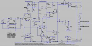
This only applies to the original circuit from Mark Tillotson (post#1) .
https://images.weserv.nl/?w=800&t=fit&url=sphinx.mythic-beasts.com/~markt/mosfet_schematic.png
Specifically, Q2 should be connected to R4 and not R3.
BTW, your last asc file works fine.
This only applies to the original circuit from Mark Tillotson (post#1) .
https://images.weserv.nl/?w=800&t=fit&url=sphinx.mythic-beasts.com/~markt/mosfet_schematic.png
Specifically, Q2 should be connected to R4 and not R3.
BTW, your last asc file works fine.
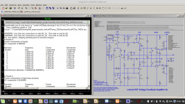
After all the hassle with LTSpice it is nice to read that. I am curious about your comments concerning the simulation circuitry.
This version of Mark's circuit illustrates my points. It also includes models and because my PC is not super fast, I have sped up the simulation by allowing larger time steps. And the 3 ffts all follow the input frequency parameter.
Attachments
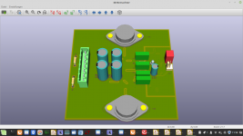
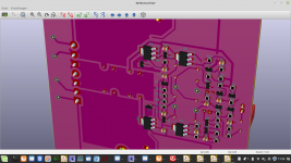
Simulations are promising so far. Meanwhile I finished a KiCAD layout on 100x100mm doubled sided pcb and will order today, possibly from All-PCB. The moment of truth comes nearer!🙂
Attachments

Last edited:
Glad everyone's having fun with this, be interesting to see any real examples people build perform well!
Well, cooling two TO-3 devices at opposite sides of a PCB might get somewhat challenging 😉!
Best regards!
Best regards!
This is the plan😉Well, cooling two TO-3 devices at opposite sides of a PCB might get somewhat challenging 😉!
Best regards!
- Status
- Not open for further replies.
- Home
- Amplifiers
- Solid State
- Blameless style lateral MOSFET amp